
Owner`s manual


ALLONE-PIECEDOORS
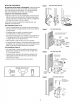
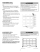
1.Assemb/ethe doorarm, Figure5:
IMPORTANT:Thegroove on the straight door arm MUST face
away from the curved door arm.
• Fastenthe straight and curved door arm sections together to
the longest possible length (with a 2 or 3 hole overlap).
• With the door closed, connect the straight door arm section
to the door bracket with the 5/16"x1-1/4" clevis pin.
• Securewith a ring fastener.
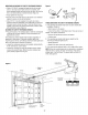
2. Adjustmentprocedures,Figure6:
• Onone-piecedoors, beforeconnecting the door arm to the
trolley, the travel limits must be adjusted. Limit adjustment
screws are located on the left side panelas shown on
page27. Followadjustment procedures below.
• Open dooradjustment:decreaseUPtravel limit
Turn the UP limit adjustment screw counter-clockwise 4
turns.
Pressthe Door Control push button. Thetrolley will travel to
the fully open position.
Manually raise the door to the open position (parallel to the
floor), and lift the door arm to the trolley. The arm should
touch the trolley just in back of the door arm connector hole.
Referto the fully opentrolley/door arm positions in the
illustration. If the arm does not extendfar enough, adjust the
limit further. Onefull turn equals 2" (5 cm) of trolley travel.
• Closeddooradjustment:decreaseDOWNtravel limit
Turn the DOWNlimit adjustment screw clockwise
4 complete turns.
Pressthe Door Control push button. Thetrolley will travel to
the fully closed position.
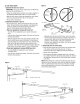
Figure6
Inner Trolley Outer Trolley
I _ Emergency Release Handle
F Closed Door
InnerTrolley
Figure5
CORRECT INCORRECT
Door Bracket
_/16 'ing Fastener
Lock Nuts
Washers 5/16"-18
. \ I_!l
Clevi_Pin AStr ightfJ'- \ III
5/16"x1-1/4' ,_ :--_4_,._%e.©j /]
Bolts __ CUo_red
5/16"-18x7/8" Arm
Manually close the door and lift the door arm to the trolley.
The arm should touch the trolley just aheadof thedoor arm
connector hole. Referto the fully closedtrolley/door arm
positions in the illustration. If the arm is behind the
connector hole, adjust the limit further. Onefull turn equals
2" (5 cm) of trolley travel.
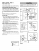
3. Connectthe doorarm to the tro//ey:
• Closethe door and join the curved arm to the connector hole
in thetrolley with the remainingclevis pin. It may be
necessaryto lift the door slightly to makethe connection.
• Securewith a ring fastener.
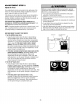
• Runthe openerthrough a complete travel cycle. If the door
has a slight "backward" slant in full open position asshown in
the illustration, decreasethe UP limit until the door is parallel
to the floor.
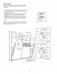
NOTE:Whensetting the up limit on the following page, the door
should not havea "backward" slant whenfully open asillustrated
below. A slight backward slant will causeunnecessarybucking
and/or jerking operationas the door is being openedor closed
from the fully openposition.
Outer Trolley
Open Door
26
Backward Slant
(Incorrect)