Owner's Manual/Manual Del Propietario CRRFTSMRN° 1/2 HP GARAGE ABRIDOR DOOR OPENER DE PUERTA DE COCHERA For Residential Use Only/S61o ModellModelo para uso residencial 139.53976SRT m Z !==, m m "o Z_ 0 CAUTION" Read and follow all safety rules and operating instructions before first use of this product. Fasten the manual near the garage door after installation. PRECAUCION: Leer y seguir todas las regias de seguridad y las instrucciones de operaci6n antes de usar este producto por primera vez.
TABLE OF CONTENTS In troduc tion 2= 7 Adjustment 28-30 Safety symbol and signal word review ........................ 2 Adjust the travel limits ............................................... 28 Preparing your garage door ........................................ Tools needed ............................................................... Adjust the force ......................................................... 29 Test the safety reversal system ................................. 30 Planning .
Preparing your garage door Before you begin: • Disable locks. To prevent possible SERIOUSINJURYOR DEATH: , ALWAYScall a trained door systems technician if garage door binds, sticks, or is out of balance. An unbalanced garage door may not reverse when required. , NEVERtry to loosen, move or adjust garage door, door springs, cables, pulleys, brackets or their hardware, all of which are under EXTREMEtension. • Remove any ropes connected to garage door.
Do you have an access door in addition to the garage door? If not, Model 53702 Emergency Key Release is required. See Accessories page. Planning Identify the type and height of your garage door. Survey your garage area to see if any of the conditions below apply to your installation. Additional materials may be required. You may find it helpful to refer back to this page and the accompanying illustrations as you proceed with the installation of your opener.
Planning (continued) ONE-PIECE DOOR iNSTALLATiONS Without a properly working safety reversal system, persons (particularly small children) could be SERIOUSLYINJUREDor KILLEDby a closing garage door. • Generally, a one-piece door does not require reinforcement. If your door is lightweight, refer to the information relating to sectional doors in Installation Step 11. . The gap between the bottom of the garage door and the floor MUST NOTexceed 1/4".
Carton Inventory Your garage door opener is packaged in two cartons which contains the motor unit and the parts illustrated below. Note that accessories will depend on the model purchased. If anything is missing, carefully check the packing material. Parts may be stuck in the Passive Infrared Control Console Security+ Three-Function Remote Control with Visor Clip (2) foam. Hardware for assembly and installation is shown on the next page.
Hardware Inventory Separate all hardware and group as shown below for the assembly and installation procedures.
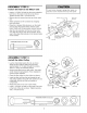
ASSEMBLY STEP Assemble Rail the 1 & Install the Trolley To avoid installation difficulties, do not run the garage door opener until instructed to do so, The front rail has a cut out "window" at the door end (see illustration). The hole above this window is larger on the top of the rail than on the bottom. A smaller hole 3-1/2" away is close to the rail edge. Rotate the back rail so it has a similar hole close to the opposite edge, about 4-3/4" from the far end. A 3-piece rail uses two back rails.
ASSEMBLY Fasten the STEP Rail 2 to the Motor Unit To avoid serious damageto garage door opener, use only those screws mounted in the top of the opener. • Insert a 1/4%20xl-3/4 bolt into the cover protection bolt hole on the back end of the rail as shown. Tighten securely with a 1/4%20 lock nut. • Remove the two screws from the top of the motor unit. Motor Unit Screws • Attach spreaders to the U bracket by snapping them into place.
ASSEMBLY Install and the Attach STEP 4 Chain/Cable the Sprocket To avoid possible serious injury to fingers from moving garage door opener: , ALWAYSkeep hand clear of sprocket while operating opener• , Securely attach sprocket cover BEFOREoperating• Cover 1. Pull the cable around the idler pulley and toward the trolley. 2. Connect the cable loop to the retaining slot on the trolley, as shown: • From below, push pins of master link bar up through cable loop and trolley slot.
ASSEMBLY Tighten the STEP 5 Chain Figure 1 • Spin the inner nut and lock washer down the threaded shaft, away from the trolley. Outer Lock Nut Washer Trolley Shaft • To tighten the chain, turn outer nut in the direction shown (Figure 1). • When the chain is approximately 1/2" above the base of the rail at its midpoint, re-tighten the inner nut to secure the adjustment. Sprocket noise can result if chain is too loose.
iNSTALLATiON Determine the STEP Header 1 Bracket Finished Ceiling Vertical Centerline Location 2x4 ...... Structural Supports To prevent possible SERIOUSINJURYor DEATH: , Header bracket MUST be RIGIDLYfastened to structural support on headerwall or ceiling, otherwise garage door might not reverse when required. DO NOT install header bracket over drywall. , Concrete anchors MUST be used if mounting header bracket or 2x4 into masonry.
ONE-PIECE DOORWITHOUTTRACK 1.Closethe doorandmarkthe insidevertical centerline of yourgaragedoor.Extendtheline ontothe headerwallabovedoor,asshown. If headroom clearance is minimal,youcaninstall theheaderbracketontheceiling.Seepage14. Ifyouneedto installtheheaderbracketona 2x4 (onwallor ceiling),uselagscrews(notprovided) tosecurelyfastenthe2x4to structuralsupports as shown. 2.Openyourdoortothe highestpointof travelas shown.Measurethe distancefromthetopofthe doortothefloor.Subtracttheactualheightof the door.
iNSTALLATiON Install the STEP Header 2 Bracket Wall Mount You can attach the header bracket either above the garage door, or to the ceiling. instructions which will work best for your requirements. Do not install the header over drywall. If installing into masonry, concrete anchors (not provided).
iNSTALLATiON Attach the STEP Rail to the 3 Header Bracket NOTE: (Optional) With an existing Craftsman installation, you may re-use the old header bracket with the two plastic spacers included in the hardware bag. Place the spacers inside the bracket on each side of the rail, as illustrated. __ • Position the opener on the garage floor below the header bracket. Use packing material as a protective base. NOTE: If the door spring is in the way you'll need help.
iNSTALLATiON Position the STEP 4 Opener To prevent damage to garage door, rest garage door opener rail on 2x4 placed on top section of door. Follow instructions which apply to your door type as illustrated. SECTIONAL TRACK DOOR OR ONE-PIECE DOOR WITH A 2x4 laid flat is convenient for setting an ideal doorto-rail distance. Outer Trolley • Raise the opener onto a stepladder. You will need help at this point if the ladder is not tall enough.
iNSTALLATiON Hang the STEP 5 Opener To avoid possible SERIOUSINJURYfrom a falling garage door opener,fasten it SECURELYto structural supports of the garage.Concrete anchors MUST be used if installing any brackets into masonry. Two representative installations are shown. Yours may be different. Hanging brackets should be angled (Figure 1) to provide rigid support. On finished ceilings (Figure 2), attach a sturdy metal bracket to structural supports before installing the opener.
iNSTALLATiON install the Door STEP 6 Control Toprevent possible SERIOUSINJURYor DEATHfrom electrocution: Locate door control within sight of door, at a minimum height of 5 feet where small children cannot reach, away from moving parts of door and door hardware. If installing into drywall, drill 5/32" holes and use the anchors provided. For pre-wired installations (as in new home construction), it may be mounted to a single gang box (Figure 2).
iNSTALLATiON Install the STEP Light and 7 Lens • Install a 75 watt maximum light bulb in the socket. The light will turn ON and remain lit for approximately 4-1/2 minutes when power is connected. Then the light will turn OFF. • Apply slight pressure on the sides of the lens and slide the tabs into the slots in the end panel. (See illustration.) • For convenience, after Adjustment Light Lens Lens Guide the lens may be installed Step 4 on page 30. ' Lens Slot • To remove, reverse the procedure.
iNSTALLATiON Electrical STEP 9 Requirements To avoid installation difficulties, opener at this time. To prevent possible SERIOUSINJURYor DEATHfrom electrocution or fire: do not run the . Be sure power is not connected to the opener,and disconnect power to circuit BEFOREremoving cover to establish permanent wiring connection. . Garagedoor installation and wiring MUST be in compliance with all local electrical and building codes. .
INSTALLATION STEP Install Reversing The Safety 10 Sensor . Be sure power is not connected to the garage door opener BEFOREinstalling the safety reversing sensor. , To prevent SERIOUSINJURYor DEATHfrom a closing garage door: - Correctly connect and align the safety reversing sensor. This required safety device MUST NOT be disabled. The safety reversing sensor must be connected and aligned correctly before the garage door opener will move in the down direction.
iNSTALLiNG THE BRACKETS Figure 1 DOOR TRACK MOUNT Be sure power to the opener is disconnected. Garage door track installation I Door Install and align the brackets so the sensors will face each other across the garage door, with the beam no higher than 6" above the floor. They may be installed in one of three ways, as follows. (RIGHT SIDE) Track Indicator Light jLip (preferred): • Slip the curved arms over the rounded edge of each door track, with the curved arms facing the door.
MOUNTING AND WiRiNG THE SAFETY SENSORS Figure 4 , Slide a 1/4"-20xl/2" carriage bolt head into the slot on each sensor. Use wing nuts to fasten sensors to brackets, with lenses pointing toward each other across the door. Be sure the lens is not obstructed by a bracket extension. See Figure 4. 1/4"-20x 1/2" Carriage bolt • Finger tighten the wing nuts. • Run the wires from both sensors to the opener. Use insulated staples to secure wire to wall and ceiling.
iNSTALLATiON Fasten the STEP Door 11 Bracket To prevent damage to garage door, reinforce inside of door with angle iron both vertically and horizontally. Follow instructions which apply to your door type as illustrated below or on the following page. A horizontal reinforcement brace should be long enough to be secured to two vertical supports. A vertical reinforcement brace should cover the height of the top pane[. HARDWARE The illustration shows one piece of angle iron as the horizontal brace.
ONE-PIECE DOORS Pleasereadandcomplywiththewarningsand reinforcement instructions onthepreviouspage. Theyapplyto one-piecedoorsalso. • Centerthedoorbracketonthetopofthe door,in linewiththe headerbracketas shown.Markeither theleftandright,or thetopandbottomholes. • Drill5/16"pilotholesandfastenthe bracketwith hardwaresupplied. If the doorhasnoexposedframing,drill3/16"pilot holesandfastenthebracketwith5/16"x1-1/2" lag screws(notprovided) tothetopof thedoor.
iNSTALLATiON Connect STEP 12 Door Arm to Trolley Follow instructions which apply to your door type as illustrated below and on the following page. SECTIONAL DOORS ONLY • Make sure garage door is fully closed. Pull the emergency release handle to disconnect the outer trolley from the inner trolley. Slide the outer trolley back (away from the pulley) for 8" minimum as shown in Figures 1, 2 and 3. • Figure I: = Fasten straight door arm section to outer trolley with the 5/16"x1" clevis pin.
ALLONE=PIECE DOORS 1.Assemble the door arm, Figure 4: • Fasten the straight and curved door arm sections together to the longest possible length (with a 2 or 3 hole overlap). Door Bracket • With the door closed, connect the straight door arm section to the door bracket with the 5/16"x1-1/4" clevis pin. _ Ring Fastener .,-,,t""vt_ __ _ }._ -"_"_"_'-'__ "_._ / ___ .qt_i_ ht"'4_ Lock Washers 5/16" Nuts 5/16"-18 t1_/I • Secure with a ring fastener. 2.
ADJUSTMENT Adjust Limits the UP STEP and DOWN 1 Travel Without a properly installed safety reversal system, persons (particularly small children) could be SERIOUSLYINJUREDor KILLEDby a closing garage door. Limit adjustment settings regulate the points at which the door will stop when moving up or down. . Incorrect adjustment of garage door travel limits will interfere with proper operation of safety reversal system. .
ADJUSTMENT Adjust the STEP 2 Force Without a properly installed safety reversal system, persons (particularly small children) could be SERIOUSLYINJUREDor KILLEDby a closing garage door. Force adjustment controls are located on the back panel of the motor unit. Force adjustment settings regulate the amount of power required to open and close the door. . Too much force on garage door will interfere with proper operation of safety reversal system. .
ADJUSTMENT Test the Safety STEP 3 Reversal System Without a properly installed safety reversal system, persons (particularly small children) could be SERIOUSLYINJUREDor KILLEDby a closing garage door. TEST • With the door fully open, place a one-inch board (or a 2x4 laid flat) on the floor, centered under the garage door. , Safety reversal system MUST be tested every month. , if one control (force or travel limits) is adjusted, the other control may also need adjustment.
OPERATION iMPORTANT SAFETY iNSTRUCTiONS To reduce the risk of severe injury or death: 1. READAND FOLLOWALL WARNINGSAND iNSTRUCTiONS. 8. If one control (force or travel limits) is adjusted, the other control may also need adjustment. 9. After any adjustments are made, the safety reversal system MUST be tested. 10. Safety reversal system MUST be tested every month. Garage door MUST reverse on contact with one-inch high object (or a 2x4 laid flat) on the floor. 11.
Lock feature Using the Wall-Mounted Door Control THE PASSIVE INFRARED CONTROL CONSOLE Press the push bar to open or close the door. Press again to reverse the door during the closing cycle or to stop the door while it's opening. _'_,_ Push __'_,__---Bar I _:_-_l Detector _ _.,__Switch _ _,_,._ To activate, press and hold the Lock button for 2 seconds. The push bar indicator light will flash as long as the Lock feature is on. To turn off, press and hold the Lock button again for 2 seconds.
Care of Your Opener Having 1. The opener doesn't operate from either the Door Control or the remote contro# LiMiT AND FORCE ADJUSTMENTS: Weather conditions may cause some minor changes in door operation requiring some re-adjustments, particularly during the first year of operation. FORCE • Does the opener have electric power? Plug a lamp into the outlet. If it doesn't light, check the fuse box or the circuit breaker. (Some outlets are controlled by a wall switch.
Having a Problem? 11. The door reverses for no apparent reason and opener light blinks for 5 seconds after reversing: • Check the safety reversing sensor. Remove any obstruction or align the receiving eye. See Installation Step 10. (Continued) 6. The garage door opens and closes by itself: • Be sure that all remote control push buttons are off. • Remove the bell wire from the door control terminals and operate from the remote only.
PROGRAMMING Your garage door opener has already been programmed at the factory to operate with your hand-held remote control, The door will open and close when you press the large push button. Below are instructions for programming your opener to operate with additional Security+ To Add USING THE "LEARN" an Additional Hand-held BUTTON 1. Press and hold the button on the hand-held remote* that you wish to operate your garage door. 2.
To Add or Change Note: Your new Keyless Entry must be programmed USING THE "LEARN" a Keyless BUTTON USING THE CONTROL CONSOLE Note: This method requires two people if the Keyless Entry is already mounted outside the garage. 2. Within 30 seconds, enter a four digit personal identification number (PIN) of your choice on the keypad. Then press and hold the ENTER button. 3. Release the button when the motor unit lights blink. It has learned the code.
REPAIR PARTS 4 7 Installation KEY NO. PART NO. 1 2 3 4 5 6 7 8 1A995 41C5141-1 183C158-3 183C157-3 144C56 41A5249 144C62 12D598-1 DESCRIPTION Master link kit Complete trolley assembly Rail - front (header) section Rail - center/back section (2) Chain idler pulley Chain and cable Spreader (2) U bracket Parts KEY NO. 9 0 10 14 PART NO.
Motor Unit Assembly Parts I 7 17 18 _11 13 Brown (Down) Contact Contact KEY NO. PART NO. 1 31D380 2 41 C4220A LIMIT SWITCH ASSEMBLY Contact 14 12 Wire KEY NO. PART NO.
ACCESSORIES 139.53702 Emergency 139.53681 Key Release: SECURITY+ Control: Required for a garage with NO access door. Enables homeowner to open garage door manually from outside by disengaging trolley, 139.53703 Outdoor Includes visor clip. Key Switch: SECURITY+ Compact 3-Function Remote Control: 139.53680 Operates the garage door automatically from outside when remote control is not handy. 53724 With loop for attaching key ring, 8 Foot Rail Extension: 139.
CONTENIDO IntroduccJ6n Revisi6n 2.7 de los simbolos Preparaci6n y terminos de seguridad de la pue_a de su cochera Herramientas Planificaci6n necesarias Sujete la mensula ......... 2 ......................... 3 ................................................. 3 ................................................................. 4-5 Conecte de la puerta ................................. 24-25 el brazo de la puerta al trole ...................... Ajustes 26-27 28.
Preparaci6n • Desarme de la puerta de su cochera las cerraduras. • Retire cualquier la puerta. cuerda o cable que este conectado Para evitar una LESIONGRAVEE INCLUSOLA MUERTE: • SIEMPRE Ilame a un tecnico profesional para que le de servicio a su puerta de cochera si esta se atora, se pandea, o est_idesequilibrada. Una puerta de cochera que no este bien equilibrada puede no retroceder como se requiere.
PlanificacJ6n _,Hay otra puerta que de acceso a la cochera? Si no es asi, sera necesario contar con el sistema de Ilave de emergencia Modelo 53702. Vea la pagina de Accesorios. Identifique la altura y el tipo de su puerta de cochera. Revise el area de su cochera y observe si alguna de los siguientes instalaciones corresponden a la suya.
PlanificacJ6n INSTALACION (conlinua) CON PUERTAS DE UNA SOLA PIEZA Sin un sistema de reversa de seguridad que funcione debidamente, al cerrar la puerta de la cochera se corre el riesgo de que las personas (yen particular los nitros pequenos) suffan LESIONESGRAVESe INCLUSOLA MUERTE. • El espacio entre la basede la puerta de la cochera y el piso NO DEBEexceder 0.625 cm (1/4 de pulgada). De no ser asi, el sistema de reversa de seguridad no va a funcionar debidamente.
Inventario de las cajas Su abridor viene empacado en dos cajas de cart6n que contienen el motor y las piezas que se muestran en la siguiente ilustraci6n. Tome nota de que los accesorios van a depender del modelo que haya comprado. Si falta alguna pieza, revise con cuidado el material de empaque ya que en ocasiones las piezas se atoran en La Consola de Control Pasivo Ifrarojo SECURITY+ Control remoto de tres funciones, con clip para el visor (2) el huJe espuma.
Inventario de piezas Antes de la instalaci6n, organice todas las piezas en grupos como se muestra en la siguiente ilustraci6n. TORNILLERiA Desplegador de la ¢adena (2) Perno de 1/4-20xl-3/4 Y PIEZAS PARA EL ARMADO Tuerca de Roldana de Tuerca de 1/4-20 (2) 3/8 pulg. (1) 3/8 pulg. (1) pulg. (2) Enlace maestro (2) Perno Ioco (1) Flecha roscada del trole (1) TORNILLERiA Y PIEZAS PARA LA INSTALACION O Pemo de 1/4-20xl/2 Tuerca de mariposa 1/4-20 (2) pulg.
NIONTAJE, PASO Monte e instale el riel 1 el trole No encienda ni use el abridor hasta que llegue al paso de la instalaci6n correspondiente, de otra manera corre el riesgo de complicar el proceso de instalaci6n. El riel delantero tiene una "ventana" cortada en el extremo de la puerta (yea la ilustraciOn). El orificio que se encuentra arriba de esta ventana es m#s grande en la parte superior del riel que en la parte inferior. Hay un orificio mas pequedo que se encuentra a 8. 75 cm (3-1/2 pulg.
NIONTAJE, Sujete PASO 2 el riel al motor • Coloque un perno de 1/4-20xl-3/4 de pulg. dentro det orificio de ta cubierta de protecci6n que se encuentra en et extremo posterior det riet, como se indica en la itustraci6n. Apriete bien et pemo con con tuerca de 1/4-20 de pulg. Use s01olos tornillos que vienen montados en la parte superior del abfidor para evitar que el abfidor de la puerta de cochera se dafle sefiamente. Polea del motor Tornillos _.
MONTAJIE, Instale la cubierta la PASO cadena de 4 o cable y coloque Para evitar posibles lesiones graves en los dedos causadas por las pares moviles del abridor de puerta de cochera: • SIEMPREtenga las manos lejos de la polea mientras este funcionando el abridor. la polea 1. Jale et cable alrededor de la polea loca y hacia et trole. 2. Conecte ta lazada det cable a ta ranura de retenci6n det trole, como aparece en ta itustraci6n: • Ponga la cubierta de la polea ANTESde hacer funcionar el abridor.
NIONTAJE, Apriete PASO 5 la cadena Figure 1 • Gire la tuerca interna y ajuste ta roldana; baje ambas por la flecha roscada, alejandolas det trole. Para apretar Tuerca extema Flecha de! trole Roldana Para apretar ta cadena, gire la tuerca externa en la direcci6n que se indica en la Figura 1. Una vez que la cadena este aproximadamente 1.25 cm (1/2 pulg.) arriba de ta base det riet en su punto medio, vuetva a apretar ta tuerca interna para asegurar el ajuste.
|NSTALAC|6N, PASO Determine va a instalar la d6nde rnensula del 1 Cielo raso Linea central vertical Pedazo de madera de 5x10 cm Soportes de la estrucura cabezal Para evitar una posible LESIONGRAVEe incluso la MUERTE: • La mensuladel cabezalDEBEquedar RiGIDAMENTE sujetaal soporteestructuralen lapareddehnterao en elcielo raso,de no ser asi esposibleque lapuertade lacocherano retrocedacuando se requiera.NO instalelamensuh del cabezalen murosfalsos.
PUERTA DE UNA SOLA PIEZA SIN CARRIL Cielo raso sin acabados 1. Cierre la puerta y marque la linea central vertical en la parte interior de la puerta de la cochera. Extienda esta linea hasta la pared delantera arriba de la puerta, como se muestra en la ilustraciOn. Pared delantera Si el espacio en la parte superior es muy reducido, puede instalar la mensula del cabezal en el techo. Vea la pagina 14.
|NSTALAC|ON, Instale la PASO rnensula del 2 cabezal Montaje en la pared La mensula del cabezal se puede sujetar a la pared justo arriba de la puerta de la cochera o en el cielo raso. Siga las instrucciones que sean las mas adecuadas para las necesidades de su cochera. No instale la m_nsula del cabezal en un muro falso. Si va a sujetar la m_nsula del cabezal a ladrillo o mamposteria, aseg_rese de utilizar sujetadores de cemento (no se incluyen).
|NSTALAC|6N, Coloque del el riel PASO 3 en la rnensula cabezal NOTA: (Opcional) Si hay una instalaci6n previa de Craftsman, puede volver a usar la mensula del cabezal de la instalaci6n previa con los dos espaciadores de plastico que se incluyen en la bolsa de tornillos. Coloque los espaciadores dentro de la mensula a cada lado del riel, como se muestra en la ilustraci6n. __ • Coloque el abridor sobre el piso de la cochera debajo de la mensula del cabezal.
|NSTALAC|6N, Coloque PASO 4 el abridor Para evitar que la puerta de cochera sufra danos, apoye el riel del abridor de la puerta de cochera sobre un pedazode madera de 5 x 10 cm (2 x 4 pulg.) colocado en la seccion superior de la puerta. Siga las instrucciones correspondientes al tipo de puerta de su cochera, como se muestra en la ilustraci6n. PUERTA SECCIONAL O PUERTA DE UNA SOLA PIEZA CON CARRIL Un pedazo de madera de 5x10 cm (2x4 pulg.
|NSTALAC|6N, Cuelgue PASO 5 el abridor Para evitar la posibilidad de una LESIONGRAVEsi se cae el abridor de la puerta de cochera, sujetelo FIRMEMENTEa los soportes estructurales de la cochera. Se deben usar sujetadores para concreto si alguna de las mensulas se va a instalar en mamposteria. Aqui se muestran dos ejemplos distintos para la instalaci6n; sin embargo, es posible que su cochera no concuerde con ninguno de ellos.
w |NSTALAC|ON, lres_ale la ureidad PASO de core_rol 6 de la puer_a Paraevitarla posibiiidadde una LESIONgrave e incluso LA MUERTE por electrocuciOn: oANTESde instalarel control de la puerta,cerciOresede que la energiaelectricano este conectada. oConecteel control SOLOa cablesde bajo voltajede 24 VOLTIOS.
|NSTALAC|ON, Instale la lute PASO 7 y lente • Instale un foco de 75 vatios (maximo) en socket del abridor. Si este se encuentra conectado, la luces permaneceran encendidas por aproximadamente 4 minutos y medio, y se apagar&n por si solas. • Aplique cierta presi6n a los lados de cada lente y deslice las leng0etas en los paneles laterales. (Vea la ilustraci6n).
|NSTALAC|6N, RequJsitos para PASO la 9 instalacJ6n electrica Para evitar la posibilidad de una LESIONgrave e incluso LA MUERTEpor electrocucion o incendio: • Cerciorese de que el abridor no este conectado a la energia electric& y desconecte la alimentacion electrica al circuito ANTESde quitar la cubierta para estaNecer la conexion del cableado permanente. • Tanto la instalacion como el cableado de la puerta de cochera DEBENcumplir con todos los codigos locales de construccion y electricos.
|NSTALAC|6N, Instale reversa PASO el sensor del 10 sisterna de • Cerciorese de que la energia electrica no este conectada al abridor de la puerta de la cochera ANTESde instalar el sensor del sistema de reversa de seguridad. • Para evitar una LESIONGRAVEe incluso LA MUERTEcuando la puerta de la cochera se esta cerrando: - Conecte y alinee correctamente el sensor del sistema de reversa de seguridad. Este dispositivo de seguridad es necesario y NO SE DEBEdesactivar.
INSTALACION DE LAS M[=NSULAS Aseg_rese de que el abridor corriente el_ctrica. no est_ conectado Figura 1 a la Instale y alinee !as mensulas de manera que los sensores esten uno frente al otro en los lados opuestos de la puerta, a una distancia maxima de 15 cm (6 pulg.) del piso.
MONTAJE Y CABLEADO DE LOS SENSORES SISTEMA DE REVERSA DE SEGURIDAD DEL Figura 4 • Deslice ta cabeza de un pemo de coche de 14-20xl/2 pulgada dentro de la ranura de los sensores. Use tuercas de madposa para sujetar los sensores a tas mensulas, con las lentes de cada sensor frente a frente a ambos lados de la puerta. Cerci6rese de que la extensi6n de la mensula no obstruya tas lentes. Vea la Figura 4. • Apdete tas tuercas de madposa a mano. Lteve los cables de los dos sensores al abridor.
|NSTALAC|6N, Sujete PASO la rnensula 11 de la puerta Para evitar que la puerta de lacochera se dafle, refuerce el interiorde la puerta con angulos de hierro tanto vertical como horizontalmente. Siga las instrucciones que correspondan al tipo de puerta de cochera que usted tenga, como se muestra en la ilustraci6n o en la pagina siguiente. Si usa un puntal horizontal, _ste debe de set Io suficientemente largo para sujetarlo a dos soportes verticales.
PUERTAS DE UNA SOLA PIEZA Lea y respete todas las advertencias e instrucciones respecto a los refuerzos, contenidas en ia p&gina anterior, Instalaci6n de puerta plagables, ya que todos los refuerzos para su puerta de una sola pieza son los mismos. • Coloque la mensula de la puerta al centro de la parte superior de la misma, alineada con la mensula dei cabezal, seg_n se indica en la ilustraci6n. Marque ya sea los orificios derecho e izquierdo o superior e inferior.
|NSTALAC|ON, PASO Conecte de la puerta el brazo 12 al trole Polea /', Siga las instrucciones que correspondan al tipo de puerta de cochera que usted tenga, como se muestra a continuaci6n y en las dos paginas siguientes. SOLO PARA PUERTAS / del trole I_ 0 1: Trole / interiorl I 11 Manija de M6nsu,ade em°rgeoc'a IoJ --- Braze U recto Braze curvo pulg. Polea ' i i 8" I_IN.___._ 1 ,, - Junte las dos secciones del brazo, Iocalizando dos pares de orificios que se puedan alinear.
TODASLAS 1. Arme PUERTAS DE UNA SOLA PIEZA el brazo de la puerta, Figura 4: • Sujete las dos secciones del los brazos de la puerta (recto y curvo) a la mayor distancia posible, de (manera que dos o tres de los orificios se sobrepongan uno al otro) Mensula • Cierre la puerta y sujete la secci6n recta del brazo a la mensula de la puerta con el pasador de chaveta de 5/16x1-1/4 de pulgada • AsegQrelos de ajuste, Figura ""'_'_9_-------------------,_'_O" chaveta de _"_ el limite 3.
AJUSTE:S, Ajuste arriba PASO el lirnite y hacia 1 del recorrido hacia Si el sistema de reversa de seguridad no se ha instalado debidamente, las personas (y los niflos pequeflos en particular) poddan suffir LESIONESGRAVESe incluso LA MUERTEcuando se cierra la puerta de la cochera. • El ajuste incorrecto de los limites del recorrido de la puerta de la cochera habra de interfedr con la operacion adecuada del sistema de reversa de seguddad.
AJUSTE:S, Ajuste PASO 2 la fuerza Si el sistema de reversa de seguridad no se ha instalado debidamente, las personas (y los ninos pequenos en particular) podrian suffir LESIONESGRAVESe incluso LA MUERTEcuando se cierra la puerta de la cochera.
AJUSTES, Pruebe PASO el sisterna 3 de reversa de SJel sJstemade reversa de seguridad no se ha instalado debidamente, las personas (y los niflos pequenos en particular) poddan suffir LESIONESGRAVESe incluso LA MUERTEcuando se cierra la puerta de la cochera. • El sistema de reversa de seguridad SE DEBEprobar cada mes. • Si se ajusta uno de los controles (limites de la fuerza o del recorrido), es posible que sea necesafio ajustar tambien el otro control.
OPERAC|ON Para reducir el riesgo de lesiones graves o la muerte: 1. LEA Y RESPETETODAS LAS ADVERTENCIASY LAS INSTRUCCIONESDE OPERACION 9. Despuesde Ilevar a cabo cualquier ajuste, SE DEBEprobar el sistema de reversa de seguridad. 10. El sistema de reversa de seguridad SE DEBEprobar cada mes. La puerta DEBEretroceder al entrar en contacto con un objeto de 2.5 cm (1 pulg) de altura o bien un pedazode madera de 5 x 10 cm (2x4) acostado en el piso. 11.
C6rno usar la unidad de control Seguro de pared Esta funci6n esta diseSada para evitar ta operaci6n de la puerta con los controles remotos manuales. No obstante, la puerta se puede abrir y cerrar con los siguientes accesorios: et Control de la puerta, et Interruptor de ta ltave externa, y ta Entrada sin llave. LA CONSOLA DE CONTROL PASIVO INFRAROJO Oprima la barra para abrir o cerrar la puerta.
Mantenirniento de cochera AJUSTES de su abridor Si tiene de puerta CONTROLES CONTROLES vez al &Ha desactivado todas los seguros de las puertas? Revise las advertencias de las instrucciones de instalaci6n que aparecen en la pagina 11. • &Hay nieve o hieto acumulado debajo de la puerta? La puerta puede congetarse y quedarse pegada al piso. Etimine esta restricci6n. • Et resorte de ta puerta de cochera puede estar roto. Haga que to cambien.
Si tiene algun problerna Ifmite es normal. Las condiciones climatolOgicas en particular pueden afectar el recorrido de la puerta. (continua) 6. La puerta de la cochera se abre y se cierra por si misma: 11. La puerta retrocede sin raz6n aparente y la luz del abridor parpadea por cinco segundos despues de que retrocede: * AsegOrese que todos los botones det control remoto esten apagados. * Revise et sensor de reversa de seguridad. Quite cualquier obstrucci6n o alinee et ojo receptor.
COMO PROGRAMAR EL ABRiDOR Su abridor de puerta de cochera ya viene programado de fabrica para operar con su control remoto manual. La puerta se abrira y se cerrara cuando oprima et bot6n grande. A continuaci6n aparecen las instrucciones Security+ adicionales. C6rno agregar COMO USAR EL BOTON "APRENDER" para programar su abridor para que opere con controles remotos un control rernoto (LEARN) manual adJcJonal COMO USAR LA CONSOLA PASWO INFRAROJO 1.
Para porter o cambiar el PIN Nota: Su nueva Entrada sin Ilave debe programarse COMO USAR EL BOTON "APRENDER" de la Entrada sin Ilaves para que opere el abridor de la puerta de su cochera. (LEARN) COMO USAR LA CONSOLA PASIVO INFRAROJO DE CONTROL !iii ¸¸¸¸ 1. Optima y suelte et bot6n "Aprender" de la unidad det motor. La luz indicadora de este bot6n estara encendida por 30 segundos. Nora: Este metodo requiere dos personas si la Entrada sin Ilaves ya esta montada afuera de la cochera. 2.
ACCESOR|OS 139.53702 Liberador SECURITY+ funciones: 139.53581 de la Ilave de emergencia: Se requiere en las cocheras que NO tienen puerta de acceso. Permite al dueSo de la casa abrir la puerta de ta cochera manualmente desde et exterior, desconectando et trole. 139.53703 SECURITY+ Control remoto compacto de 3 funciones: 139.53580 Opera la puerta de ta cochera automaticamente desde el exterior cuando et control remoto no esta a la mano. Con tazada para ponerse en et ltavero. 139.
iiiiiiiiiiiiiiiiiii_' iiiiiiiiiiiiiiiiiii iiiiiiiiiiiiiiiiiii !!!!!!!!!!!!!!!!!!!i For repair of major brand appliances in your own home.., nomatterwhomade it, no matterwhosold it! iiiiiiiiiiiiiiiiiii 1-800-4-MY-HOME SMAnytime, iiiiiiiiiiiiiiiiiiii iiiiiiiiiiiiiiiiiiii iiiiiiiiiiiiiiiiiiii dayornight ................... iiiiiiiiiiiiiiiiiii: iiiiiiiiiiiiiiiiiii iiiiiiiiiiiiiiiiiii For repair of carry-in products like vacuums, lawn equipment, and electronics, ...................