Owner’s Manual/Manual Del Propietario 1/2 HP GARAGE DOOR OPENER ABRIDOR DE PUERTA DE COCHERA For Residential Use Only/Sólo para uso residencial Model/Modelo 139.53991 ENGLISH ESPAÑOL CAUTION: Read and follow all safety rules and operating instructions before first use of this product. PRECAUCIÓN: Leer y seguir todas las reglas de seguridad y las instrucciones de operación antes de usar este producto por primera vez. Fasten the manual near the garage door after installation.
TABLE OF CONTENTS Introduction 2-7 Adjustment Section Safety symbol and signal word review........................2 Preparing your garage door ........................................3 Tools needed ...............................................................3 Planning ..................................................................4-5 Carton inventory ..........................................................6 Hardware inventory .....................................................
Preparing your garage door WARNING Before you begin: • Disable locks. • Remove any ropes connected to garage door. • Complete the following test to make sure your garage door is balanced and is not sticking or binding: 1. Lift the door about halfway as shown. Release the door. If balanced, it should stay in place, supported entirely by its springs. 2. Raise and lower the door to see if there is any binding or sticking.
Planning • Do you have an access door in addition to the garage door? If not, Model 53702 Emergency Key Release is required. See Accessories page. • Look at the garage door where it meets the floor. Any gap between the floor and the bottom of the door must not exceed 1/4". Otherwise, the safety reversal system may not work properly. See Adjustment Step 3. Floor or door should be repaired. Identify the type and height of your garage door.
Planning (Continued) WARNING ONE-PIECE DOOR INSTALLATIONS • Generally, a one-piece door does not require reinforcement. If your door is lightweight, refer to the information relating to sectional doors in Installation Step 12. • Depending on your door’s construction, you may need additional mounting hardware for the door bracket (Step 12).
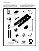
Carton Inventory Your garage door opener is packaged in one carton which contains the motor unit and the parts illustrated below. Note that accessories will depend on the model purchased. If anything is missing, carefully check the packing material. Parts may be stuck in the foam. KEEP THE FOAM INTACT (see page 10.) Hardware for assembly and installation is shown on the next page. Save the carton and packing material until installation and adjustment is complete.
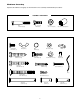
Hardware Inventory Separate all hardware and group as shown below for the assembly and installation procedures.
ASSEMBLY STEP 1 Assemble the Rail To avoid installation difficulties, do not run the garage door opener until instructed to do so. 1. Turn the opened rail carton upside down and empty its contents onto a level work surface. 2. Unfold the rails, taking care to avoid kinking the screw rod joints. 3. Rotate the rail sections so that the flat side is down and the screw side is up for all three lengths. Keep it clean and free of debris while you are working.
Assemble the Rail (Continued) 4. Beginning with the sprocket end, straighten the three rail sections so that the screw rod is in a straight line at the joints. (Avoid handling the joints, which may have sharp edges.) 5. Carefully slide the pins at the top edge of the rail into the openings on the adjacent rail. It is essential that the rail assembly be on a level surface to achieve proper alignment and to avoid damage to the pins. 6.
ASSEMBLY STEP 2 Fasten the Rail To the Motor Unit and Install the Trolley NOTE: To aid in assembly and installation, replace the foam packing around the motor unit. Remove it after Installation Step 5. • Working on a level surface, align the rail assembly with the motor unit, as shown. • Slip the coupling over the rail sprocket. • Slide the rail through the motor unit bracket until the coupling fits securely over the motor unit sprocket.
1/4"-20 Lock Nuts ASSEMBLY STEP 3 Rail Brackets Attach the Rail Brackets • Align rail brackets to end of rail assembly, as shown. • Insert two 1/4"-20 x 5/8" hex bolts and lock nuts. Tighten securely with a 7/16" socket. 1/4"-20x5/8 Hex Bolts You have now finished assembling your garage door opener. Please read the following warnings before proceeding to the installation section.
INSTALLATION STEP 1 Determine the Header Bracket Location Finished Ceiling Vertical Centerline Header Wall 2x4 WARNING Structural Supports WARNING To prevent possible SERIOUS INJURY or DEATH: • Header bracket MUST be RIGIDLY fastened to structural support on header wall or ceiling, otherwise garage door might not reverse when required. DO NOT install header bracket over drywall. • Concrete anchors MUST be used if mounting header bracket or 2x4 into masonry.
ONE-PIECE DOOR WITHOUT TRACK 1. Close the door and mark the inside vertical centerline of your garage door. Extend the line onto the header wall above door, as shown. If headroom clearance is minimal, you can install the header bracket on the ceiling. See page 14. If you need to install the header bracket on a 2x4 (on wall or ceiling), use lag screws (not provided) to securely fasten the 2x4 to structural supports as shown. 2. Open your door to the highest point of travel as shown.
INSTALLATION STEP 2 Install the Header Bracket You can attach the header bracket either to the wall above the garage door, or to the ceiling. Follow the instructions which will work best for your particular requirements. Do not install the header bracket over drywall. If installing into masonry, use concrete anchors (not provided). Wall Mounting Holes CEILING MOUNT ONLY The nail hole is for positioning only. You must use lag screws to mount the header bracket.
INSTALLATION STEP 3 Attach the Rail to the Header Bracket • Position the opener on the garage floor below the header bracket. Use packing material as a protective base. NOTE: If the door spring is in the way you’ll need help. Have someone hold the opener securely on a temporary support to allow the rail to clear the spring. • Position the rail bracket against the header bracket. • Align the bracket holes and join with a clevis pin as shown. • Insert a ring fastener to secure.
INSTALLATION STEP 4 WARNING Install the Safety Reversing Sensor • Be sure power is not connected to the garage door opener BEFORE installing the safety reversing sensor. • To prevent SERIOUS INJURY or DEATH from a closing garage door: – Correctly connect and align the safety reversing sensor. This required safety device MUST NOT be disabled. – Install the safety reversing sensor so beam is NO HIGHER than 6" above garage floor.
INSTALLING THE BRACKETS Be sure power to the opener is disconnected. Install and align the brackets so the sensors will face each other across the garage door, with the beam no higher than 6" above the floor. They may be installed in one of three ways, as follows. Figure 1 DOOR TRACK MOUNT (RIGHT SIDE) Door Track Lip Indicator light Garage door track installation (preferred): • Slip the curved arms over the rounded edge of each door track, with the curved arms facing the door.
MOUNTING AND WIRING THE SAFETY SENSORS • Slide a 1/4"-20x1/2" carriage bolt head into the slot on each sensor. Use wing nuts to fasten sensors to brackets, with lenses pointing toward each other across the door. Be sure the lens is not obstructed by a bracket extension. See Figure 4. • Finger tighten the wing nuts. Figure 4 Wing nut Carriage bolt 1/4"-20x1/2" Recommended Wire Routing 1. Using insulated staples, run the wires from both sensors to the rail at the door header (see Figure 5). 2.
WARNING CAUTION INSTALLATION STEP 5 Position the Opener To prevent damage to garage door, rest garage door opener rail on 2x4 placed on top section of door. Follow instructions which apply to your door type as illustrated. SECTIONAL DOOR OR ONE-PIECE DOOR WITH TRACK A 2x4 laid flat is convenient for setting an ideal doorto-rail distance. • Raise the opener onto a stepladder. You will need help at this point if the ladder is not tall enough.
WARNING INSTALLATION STEP 6 Hang the Opener To avoid possible SERIOUS INJURY from a falling garage door opener, fasten it SECURELY to structural supports of the garage. Concrete anchors MUST be used if installing any brackets into masonry. CAUTION Three representative installations are shown. Yours may be different. Hanging brackets should be angled (Figure 1) to provide rigid support. On finished ceilings (Figure 2), attach a sturdy metal bracket to structural supports before installing the opener.
WARNING WARNING INSTALLATION CAUTION STEP 7 WARNING Install the Door Control To prevent possible SERIOUS INJURY or DEATH from electrocution: • Be sure power is not connected BEFORE installing door control. • Connect ONLY to 24 VOLT low voltage wires. To prevent possible SERIOUS INJURY or DEATH from a closing garage door: • Install door control within sight of garage door, out of reach of children at a minimum height of 5 feet, and away from all moving parts of door.
INSTALLATION WARNING STEP 8 WARNING Electrical Requirements To prevent possible SERIOUS INJURY or DEATH from electrocution or fire: • Be sure power is not connected to the opener, and disconnect power to circuit BEFORE removing cover to establish permanent wiring connection. • Garage door installation and wiring MUST be in compliance with all local electrical and building codes. • NEVER use an extension cord, 2-wire adapter, or change plug in any way to make it fit outlet. Be sure the opener is grounded.
INSTALLATION STEP 10 Top Lens Tab Install the Lights and Lens • Install a 100 watt maximum light bulb in each socket. The lights will turn ON and remain lit for approximately 4-1/2 minutes when power is connected. Then the lights will turn OFF. • Insert bottom lens tabs into slots on chassis. Tilt towards chassis to engage top tabs, then drop down gently into place. (See illustration.) • To remove, depress both top lens tabs. Tilt lens slightly outward and down, then pull out to clear bulbs.
WARNING INSTALLATION STEP 12 CAUTION Fasten Door Bracket To prevent damage to garage door, reinforce inside of door with angle iron both vertically and horizontally. Follow instructions which apply to your door type as illustrated below or on the following page. A horizontal brace should be long enough to be secured to 2 vertical supports. A vertical brace should cover the height of the top panel. The illustration shows one piece of angle iron as the horizontal brace.
ONE-PIECE DOORS Please read and comply with the warnings and reinforcement instructions on the previous page. They apply to one-piece doors also. • Center the door bracket on the top of the door, in line with the header bracket as shown. Mark either the left and right, or the top and bottom holes. • Drill 5/16" pilot holes and fasten the bracket with hardware supplied.
INSTALLATION STEP 13 Connect Door Arm to Trolley Inner Trolley Outer Trolley Follow instructions which apply to your door type as illustrated below and on the following page. SECTIONAL DOORS ONLY • Make sure garage door is fully closed. Pull the emergency release handle to disconnect the outer trolley from the inner trolley. Slide the outer trolley back (away from the door) about 2" as shown in Figures 1, 2 and 3.
ALL ONE-PIECE DOORS 1. Assemble the door arm: • Fasten the straight and curved door arm sections together to the longest possible length (with a 2 or 3 hole overlap). • With the door closed, connect the straight door arm section to the door bracket with the 5/16"x1-1/4" clevis pin. • Secure with a ring fastener. 2. Adjustment procedures: On one-piece doors, before connecting the door arm to the trolley, the travel limits must be adjusted.
WARNING ADJUSTMENT STEP 1 Adjust the UP and DOWN Travel Limits Without a properly installed safety reversal system, persons (particularly small children) could be SERIOUSLY INJURED or KILLED by a closing garage door. • Incorrect adjustment of garage door travel limits will interfere with proper operation of safety reversal system. • If one control (force or travel limits) is adjusted, the other control may also need adjustment. • After any adjustments are made, the safety reversal system MUST be tested.
WARNING ADJUSTMENT STEP 2 Adjust the Force Without a properly installed safety reversal system, persons (particularly small children) could be SERIOUSLY INJURED or KILLED by a closing garage door. • Too much force on garage door will interfere with proper operation of safety reversal system. • NEVER increase force beyond minimum amount required to close garage door. • NEVER use force adjustments to compensate for a binding or sticking garage door.
WARNING ADJUSTMENT STEP 3 Test the Safety Reversal System Without a properly installed safety reversal system, persons (particularly small children) could be SERIOUSLY INJURED or KILLED by a closing garage door. • Safety reversal system MUST be tested every month. • If one control (force or travel limits) is adjusted, the other control may also need adjustment. • After ANY adjustments are made, the safety reversal system MUST be tested.
OPERATION IMPORTANT SAFETY INSTRUCTIONS WARNING To reduce the risk of severe injury or death: CAUTION 1. READ AND FOLLOW ALL WARNINGS AND 8. If one control (force or travel limits) is adjusted, the INSTRUCTIONS. 2. ALWAYS keep remote controls out of reach of children. NEVER permit children to operate or play with garage door control push buttons or remote controls. 3. ONLY activate garage door when it can be seen clearly, it is properly adjusted, and there are no obstructions to door travel. 4.
Using the Wall-Mounted Door Control THE PREMIUM CONTROL CONSOLE Press the lighted push button to open or close the door. Press again to reverse the door during the closing cycle or to stop the door while it's opening. To Open the Door Manually WARNING • To prevent possible SERIOUS INJURY or DEATH from a falling garage door: – If possible, use emergency release handle to disengage trolley ONLY when garage door is CLOSED.
THE REMOTE CONTROL BATTERY Care of Your Opener WARNING LIMIT AND FORCE ADJUSTMENTS Weather conditions may cause some minor changes in door operation requiring some + re-adjustments, 9 1 7 3 kg kg particularly during 5 the first year of + operation. LIMIT CONTROLS FORCE CONTROLS Pages 28 and 29 refer to the limit and force adjustments. Only a screwdriver is required. Follow the instructions carefully. Repeat the safety reverse test (page 30) after any adjustment of limits or force.
Having a Problem? 8. The door stops but doesn't close completely: • Review the travel limits adjustment procedures on page 28. Repeat the safety reverse test after any adjustment of door arm length, close force or down limit. 1. The opener doesn't operate from either the Door Control or the remote control: • Does the opener have electric power? Plug a lamp into the outlet. If it doesn't light, check the fuse box or the circuit breaker. (Some outlets are controlled by a wall switch.
PROGRAMMING Your garage door opener has already been programmed at the factory to operate with your hand-held remote control. The door will open and close when you press the large push button. Below are instructions for programming your opener to operate with additional Security✚ remote controls. To Add an Additional Hand-held Remote Control USING THE “LEARN” BUTTON USING THE PREMIUM CONTROL CONSOLE LIGH T LOCK 1. Press and release the “learn” button on the motor unit.
To Add or Change a Keyless Entry PIN NOTE: Your new Keyless Entry must be programmed to operate your garage door opener. USING THE “LEARN” BUTTON USING THE PREMIUM CONTROL CONSOLE LIGH T LOC K 1. Press and release the “learn” button on motor unit. The learn indicator light will glow steadily for 30 seconds. NOTE: This method requires two people if the Keyless Entry is already mounted outside the garage. 1 5 3 kg 1. Enter a four digit personal identification number (PIN) of your choice on the keypad.
REPAIR PARTS Rail Assembly Parts 9 1 8 10 2 7 4 KEY PART NO. NO.
Motor Unit Assembly Parts 1 Brown Wire (Down) Contact 2 LIMIT SWITCH ASSY. DN UP Drive Gear 17 Center Limit Contact (Up) Contact 7 8 8d 8g Yellow Wire 15 5 3 Grey Wire 6 14 8b 4 8d 18 8a 8e 8f 11a 11 8c 10 11 9 12 13 16 KEY NO. 1 2 3 4 5 6 7 8 8a 8b 8c 8d 8e PART NO.
ACCESSORIES 139.53702 Emergency Key Release: Required for a garage with NO access door. Enables homeowner to open garage door manually from outside by disengaging trolley. 139.53681 SECURITY✚ 3-Function Remote Control: Includes visor clip. 139.53703 Outdoor Key Switch: Operates the garage door automatically from outside when remote control is not handy. 139.53680 SECURITY✚ Compact 3-Function Remote Control: With loop for attaching key ring. 139.
NCIA NCIA TABLE OF CONTENTS Introducción 2-7 Sección de Ajustes 28-30 Revisión de los símbolos y términos de seguridad ..............2 Preparación de la puerta de su cochera ..............................3 Herramientas necesarias ......................................................3 Planificación ......................................................................4-5 Inventario de las cajas de cartón..........................................6 Inventario de piezas...................................
Preparación de la puerta de su cochera ADVERTENCIA A Para evitar una LESIÓN GRAVE O INCLUSO LA MUERTE: • SIEMPRE llame a un técnico profesional para que le dé servicio a su puerta de cochera si ésta se atora, se pandea, o está desequilibrada. Una puerta de cochera que no esté bien equilibrada puede no retroceder como se requiere.
Planificación • ¿Hay otra puerta que dé acceso a la cochera? Si no es así, será necesario contar con el sistema de llave de emergencia Modelo 53702. Vea la página de Accesorios. • Observe el punto donde la puerta hace contacto con el piso. El espacio entre la base de la puerta y el piso no debe exceder 0.625 cm (1/4 de pulgada). Si no es así, se corre el riesgo de que el sistema de reversa de emergencia no funcione correctamente. Vea Ajustes, Paso 3. Va a ser necesario reparar ya sea el piso o la puerta.
Planificación (continúa) ADVERTENCIA INSTALACIÓN CON PUERTAS DE UNA SOLA PIEZA • Generalmente una puerta de una sola pieza no requiere de refuerzos adicionales. Si usted tiene una puerta de material liviano y quiere reforzarla, consulte la información respecto a puertas seccionales, contenida en Instalación, Paso 12. • Dependiendo del diseño de su puerta, tal vez necesite piezas o sujetadores adicionales para la ménsula de la puerta (Paso 12).
Inventario de las cajas Su abridor viene empacado en una caja de cartón que contienen el motor y las piezas que se muestran en la siguiente ilustración. Tome nota de que los accesorios van a depender del modelo que haya comprado. Si falta alguna pieza, revise con cuidado el material de empaque ya que en ocasiones las piezas se atoran en el hule espuma. NO DESTRUYA EL HULE ESPUMA (vea la página 10).
Inventario de piezas Antes de la instalación, organice todas las piezas en grupos como se muestra en la siguiente ilustración. TORNILLERÍA Y PIEZAS PARA EL ARMADO Perno de 1/4-20x1-3/4 pulg. (8) Perno hexagonal de 1/4-20x5/8 pulg. (4) Tuerca de 1/4-20x7/16 pulg. (12) Manguito del cople de la polea TORNILLERÍA Y PIEZAS PARA LA INSTALACIÓN NOTIC E Perno de 1/4-20x1/2 pulg. (2) Tuerca de mariposa (2) Tornillo de cabeza cuadrada de 5/16-9x1-5/8 de pulg.
MONTAJE, PASO 1 Montaje del riel No encienda ni use el abridor hasta que llegue al paso de la instalación correspondiente, de otra manera corre el riesgo de complicar el proceso de instalación. 1. Después de abrir la caja del riel, póngala boca abajo sobre una superfície de trabajo plana. 2. Desdoble los rieles con cuidado de no golpear la junta de la varilla de conexión. 3. Voltee las secciones del riel de manera que el lado plano esté hacia abajo y el lado de la varilla esté hacia arriba.
Instalación del riel (Continuación) 4. Empezando en el extremo con la rueda dentada, coloque las tres secciones del riel de manera que la varilla de conexión esté alineada. (Tenga cuidado de no tocar el extremo de la varilla de conexión ya que tiene orillas afiladas.) 5. Cuidadosamente deslice los pasadores en la orilla superior de una de las secciones del riel en los orificios de la sección adyacente del riel.
MONTAJE, PASO 2 Sujete el riel a la unidad del motor e instale el trole NOTA: Para facilitarle el montaje y la instalación del motor, vuelva a colocarlo dentro del hule espuma de protección, retire la espuma después de concluir Instalación, Paso 5. • Sobre una superfície plana, alinee el riel ya armado al motor como se muestra en la siguiente ilustración. • Deslice el cople sobre la polea del riel.
MONTAJE, PASO 3 Ménsulas del riel Tuercas de 1/4-20 pulg. Coloque las ménsulas del riel • Alinee las ménsulas con la parte trasera del riel como se muestra. • Atornille las ménsulas con los pernos hexagonales de 1/4-20x5/8 y las tuercas respectivas. Apriete firmemente con una llave de 7/16 pulg. Pernos hexagonales de 1/4-20x5/8 Ya terminó de armar su abridor de puerta de cochera, por favor lea las siguientes advertencias antes de continuar a la Sección de instalación.
Cielo raso INSTALACIÓN, PASO 1 Línea central vertical Determine dónde va a instalar la ménsula del cabezal Pedazo de madera de 5x10 cm (2x4 pulg.) Soportes de la estrucura Pared delantera ADVERTENCIA ADVERTENCIA Para evitar una posible LESIÓN GRAVE o incluso LA MUERTE: • La ménsula del cabezal DEBE quedar RÍGIDAMENTE sujeta al soporte estructural en la pared delantera o en el cielo raso, de no ser así es posible que la puerta de la cochera no retroceda cuando se requiera.
PUERTA DE UNA SOLA PIEZA SIN CARRIL 1. Cierre la puerta y marque la línea central vertical en la parte interior de la puerta de la cochera. Extienda esta línea hasta la pared delantera arriba de la puerta, como se muestra en la ilustración. Si el espacio en la parte superior es muy reducido, puede instalar la ménsula del cabezal en el techo. Vea la página 14. Si es necesario instalar la ménsula del cabezal en un pedazo de madera de 5x10 cm (2x4 pulg.
INSTALACIÓN, PASO 2 Instale la ménsula del cabezal La ménsula del cabezal se puede sujetar a la pared justo arriba de la puerta de la cochera o en el cielo raso. Siga las instrucciones que sean las más adecuadas para las necesidades de su cochera. No instale la ménsula del cabezal en un muro falso. Si va a sujetar la ménsula del cabezal a ladrillo o mampostería, asegúrese de utilizar sujetadores de cemento (no provisto).
INSTALACIÓN, PASO 3 Coloque el riel en la ménsula del cabezal • Coloque el abridor sobre el piso de la cochera debajo de la ménsula del cabezal. Use el hule espuma del empaque como base para protegerlo. NOTA: Si el resorte de la puerta está obstruyendo, va a necesitar ayuda. Otra persona tendrá que sostener el abridor firmemente sobre un soporte temporal para ayudarle a que el riel pueda librar el resorte. • Coloque la ménsula del riel junto a la ménsula del cabezal.
ADVERTENCIA INSTALACIÓN, PASO 4 Instale el sensor del sistema de reversa de seguridad • Cerciórese de que la energía eléctrica no esté conectada al abridor de la puerta de la cochera ANTES de instalar el sensor del sistema de reversa de seguridad. • Para evitar una LESIÓN GRAVE o incluso LA MUERTE cuando la puerta de la cochera se está cerrando: – Conecte y alínee correctamente el sensor del sistema de reversa de seguridad. Este dispositivo de seguridad es necesario y NO SE DEBE desactivar.
INSTALACIÓN DE LAS MÉNSULAS Asegúrese de que el abridor no esté conectado a la corriente eléctrica. Instale y alinee las ménsulas de manera que los sensores estén uno frente al otro en los lados opuestos de la puerta, a una distancia máxima de 15 cm (6 pulg.) del piso. Instale las ménsulas de acuerdo con una de las tres maneras siguientes.
MONTAJE Y CABLEADO DE LOS SENSORES DEL SISTEMA DE REVERSA DE SEGURIDAD • Deslice la cabeza de un perno de coche de 14-20x1/2 pulgada dentro de la ranura de los sensores. Use tuercas de mariposa para sujetar los sensores a las ménsulas, con las lentes de cada sensor frente a frente a ambos lados de la puerta. Cerciórese de que la extensión de la ménsula no obstruya las lentes. Vea la Figura 4. • Apriete las tuercas de mariposa a mano. Figura 4 Tuerca de mariposa Perno de coche de 1/4-20x1/2 pulg.
PRECAUCIÓN INSTALACIÓN, PASO 5 Coloque el abridor Para evitar que la puerta de cochera sufra daños, apoye el riel del abridor de la puerta de cochera sobre un pedazo de madera de 5 x 10 cm (2 x 4 pulg.) colocado en la sección superior de la puerta. Siga las instrucciones correspondientes al tipo de puerta de su cochera, como se muestra en la ilustración. PUERTA SECCIONAL O PUERTA DE UNA SOLA PIEZA CON CARRIL Un pedazo de madera de 5x10 cm (2x4 pulg.
AD ADVERTENCIA INSTALACIÓN, PASO 6 Cuelgue el abridor Para evitar la posibilidad de una LESIÓN GRAVE si se cae el abridor de la puerta de cochera, sujételo FIRMEMENTE a los soportes estructurales de la cochera. Se DEBEN usar sujetadores para concreto si alguna de las ménsulas se va a instalar en mampostería. Aquí se muestran tres ejemplos distintos para la instalación; sin embargo, es posible que su cochera no concuerde con ninguno de ellos.
ADVERTENCIA ADVERTENCIA ADVERTENCIA INSTALACIÓN, PASO 7 Instale la unidad de control de la puerta Para evitar la posibilidad de una LESIÓN GRAVE o incluso LA MUERTE por electrocución: • ANTES de instalar el control de la puerta, cerciórese de que la energía eléctrica no esté conectada. • Conecte el control SÓLO a cables de bajo voltaje de 24 VOLTIOS.
INSTALACIÓN, PASO 8 ADVERTENCIA ADVERTENCIA Requisitos para la instalación eléctrica Para evitar la posibilidad de una LESIÓN GRAVE o incluso LA MUERTE por electrocución o incendio: • Cerciórese de que el abridor no esté conectado a la energía eléctrica, y desconecte la alimentación eléctrica al circuito ANTES de quitar la cubierta para establecer la conexión del cableado permanente.
Lengüeta de la parte superior de la lente INSTALACIÓN, PASO 10 Lente Instale las luces y lentes • Instale un foco de 100 vatios (máximo) en cada socket del abridor. Si éste se encuentra conectado, la luces permanecerán encendidas por aproximadamente 4 minutos y medio, y se apagarán por sí solas. • Inserte las lengüetas inferiores de la lente en las ranuras correspondientes del chasis e inclínelas hacia el chasis para que entren las lengüetas de la parte superior. (Vea la ilustración).
PRECAUCIÓN INSTALACIÓN, PASO 12 Sujete la ménsula de la puerta Para evitar que la puerta de la cochera se dañe, refuerce el interior de la puerta con ángulos de hierro tanto vertical como horizontalmente. Siga las instrucciones que correspondan al tipo de puerta de cochera que usted tenga, como se muestra en la ilustración o en la página siguiente. Si usa un puntal horizontal, éste debe de ser lo suficientemente largo para sujetarlo a dos soportes verticales.
PUERTAS DE UNA SOLA PIEZA Lea y respete todas las advertencias e instrucciones respecto a los refuerzos, contenidas en la página anterior, Instalación de puerta plagables, ya que todos los refuerzos para su puerta de una sola pieza son los mismos. • Coloque la ménsula de la puerta al centro de la parte superior de la misma, alineada con la ménsula del cabezal, según se indica en la ilustración. Marque ya sea los orificios derecho e izquierdo o superior y inferior. • Taladre los orificios piloto de 0.
INSTALACIÓN, PASO 13 Trole interior Conecte el brazo de la puerta al trole Trole exterior Siga las instrucciones que correspondan al tipo de puerta de cochera que usted tenga, como se muestra continuación y en las dos páginas siguientes. SÓLO PARA PUERTAS SECCIONALES • Cerciórese de que la puerta de la cochera esté completamente cerrada. Jale la manija del sistema de liberación de emergencia para desconectar el trole exterior del trole interior.
TODAS LAS PUERTAS DE UNA SOLA PIEZA Ménsula de la puerta 1. Arme el brazo de la puerta: • Sujete las dos secciones del los brazos de la puerta (recto y curvo) a la mayor distancia posible, de (manera que dos o tres de los orificios se sobrepongan uno al otro). • Cierre la puerta y sujete la sección recta del brazo a la ménsula de la puerta con el pasador de chaveta de 5/16x1-1/4 de pulgada. • Asegúrelos con un anillo sujetador.
ADVERTENCIA AJUSTES, PASO 1 Ajuste el límite del recorrido HACIA ARRIBA y HACIA ABAJO Al ajustar el límite del recorrido de la puerta, se regula hasta qué punto ésta se detendrá al abrir y al cerrar. Para poner en marcha el abridor, oprima el botón de control de la puerta. Haga funcionar el abridor durante un ciclo competo del recorrido.
ADVERTENCIA AJUSTES, PASO 2 Ajuste la fuerza Si el sistema de reversa de seguridad no se ha instalado debidamente, las personas (y los niños pequeños en particular) podrían sufrir LESIONES GRAVES o incluso LA MUERTE cuando se cierra la puerta de la cochera. • Si el límite de la fuerza de la puerta de la cochera es excesivo habrá de interferir con la operación adecuada del sistema de reversa de seguridad.
AJUSTES, PASO 3 ADVERTENCIA Pruebe el sistema de reversa de seguridad Si el sistema de reversa de seguridad no se ha instalado debidamente, las personas (y los niños pequeños en particular) podrían sufrir LESIONES GRAVES o incluso LA MUERTE cuando se cierra la puerta de la cochera. • El sistema de reversa de seguridad SE DEBE probar cada mes. • Si se ajusta uno de los controles (límites de la fuerza o del recorrido), es posible que sea necesario ajustar también el otro control.
OPERACIÓN IMPORTANTES INSTRUCCIONES DE SEGURIDAD ADVERTENCIA Para reducir el riesgo de lesiones graves o la muerte: ADVERTENCIA ADVERTENCIA 8. Si se ajusta uno de los controles (límites de la fuerza o del 1. LEA Y RESPETE TODAS LAS ADVERTENCIAS Y LAS recorrido), es posible que sea necesario ajustar también el otro control. 9. Después de llevar a cabo cualquier ajuste, SE DEBE probar el sistema de reversa de seguridad. 10. El sistema de reversa de seguridad SE DEBE probar cada mes.
Cómo usar la unidad de control de pared LA CONSOLA DE CONTROL PREMIUM Oprima el botón iluminado para abrir o cerrar la puerta. Oprima de nuevo para que la puerta retroceda en el ciclo de cierre o para detener la puerta cuando se está abriendo.
LA BATERÍA DEL CONTROL REMOTO Mantenimiento de su abridor de puerta de cochera ADVERTENCIA AJUSTES DE LÍMITE Y FUERZA Las condiciones climatológicas pueden + ocasionar cambios menores en la 9 1 7 3 kg kg operación de la 5 puerta, los cuales + van a requerir CONTROLES CONTROLES algunos reajustes, DE FUERZA DE LÍMITE en particular durante el primer año de operación. En las páginas 28 y 29 se encuentra la información sobre los ajustes de límite y de fuerza. Lo único que necesita es un desarmador.
Si tiene algún problema 1. El abridor no funciona con el control de la puerta ni con el control remoto: • ¿Está el abridor conectado a la electricidad? Conecte una lámpara a la toma de corriente. Si no se enciende, revise la caja de fusibles o el cortacircuito. (Algunas tomas de corriente se controlan con un interruptor de pared). • ¿Ha desactivado todas los seguros de las puertas? Revise las advertencias de las instrucciones de instalación que aparecen en la página 11.
COMO PROGRAMAR EL ABRIDOR Su abridor de puerta de cochera ya viene programado de fábrica para operar con su control remoto manual. La puerta se abrirá y se cerrará cuando oprima el botón grande. A continuación aparecen las instrucciones para programar su abridor para que opere con controles remotos Security✚ adicionales. Cómo agregar un control remoto manual adicional CÓMO USAR EL BOTÓN “APRENDER” (LEARN) CÓMO USAR LA CONSOLA DE CONTROL PREMIUM LIGH T LOCK 1.
Para poner o cambiar el PIN de la Entrada sin llaves NOTA: Su nueva Entrada sin llave debe programarse para que opere el abridor de la puerta de su cochera. CÓMO USAR EL BOTÓN “APRENDER” (LEARN) CÓMO USAR LA CONSOLA DE CONTROL PREMIUM LIGH T LOC K 1. Oprima y suelte el botón "Aprender" de la unidad del motor. La luz indicadora de este botón estará encendida por 30 segundos. NOTA: Este método requiere dos personas si la Entrada sin llaves ya está montada afuera de la cochera. 1 7 5 3 kg 1.
ACCESSORIOS 139.53702 Liberador de la llave de emergencia: Se requiere en las cocheras que NO tienen puerta de acceso. Permite al due o de la casa abrir la puerta de la cochera manualmente desde el exterior, desconectando el trole. 139.53681 SECURITY✚ Control remoto de 3 funciones: Incluye el clip del visor. 139.53703 Interruptor de la llave externa: Opera la puerta de la cochera automáticamente desde el exterior cuando el control remoto no está a la mano. 139.
Get it fixed, at your home or ours! Your Home For repair – in your home – of all major brand appliances, lawn and garden equipment, or heating and cooling systems, no matter who made it, no matter who sold it! For the replacement parts, accessories and owner’s manuals that you need to do-it-yourself. For Sears professional installation of home appliances and items like garage door openers and water heaters. 1-800-4-MY-HOME® (1-800-469-4663) Call anytime, day or night (U.S.A. and Canada) www.sears.