/ Owners ® anual 00000 Garage Door Opener CAUTION PLEASE READ THIS MANUAL CAREFULLY Model Model Model Model Model 139.53315SR ", 1/3HP 139.53415SR1/2HP 139.53615SR = 1/2HP 139.53625SR - 1/2HP 139.53699SR _ 1/2HP FASTEN THIS MANUAL NEAR THE GARAGE DOOR AFTER INSTALLATION, PERIODIC CHECKS OF THE OPENER ARE REQUIRED TO INSURE SATISFACTORY OPERATION. FOR RESIDENTIAL , ,= ,= USE ONLY, ,,NIU = I , , I ............................ CONTENTS Safety Rules ................... Operation of Your Opener ...
Start By Reading These important Safety Rules , H,,,,,,,,,,,,I, JL , = ' ' L L== ,===1,,, =,, H NH,,= ,, THIS SAFETY ALERT SYMBOL MEANS CAUTION _-- PERSONAL SAFETY DAMAGE INSTRUCTION, READ THESE INSTRUCTIONS CAREFULLY, OR PROPERTY THIS GARAGE DOOR OPENER IS DESIGNED AND TESTED SAFE SERVICE PROVIDED IT IS INSTALLED AND OPERATED WITH THE FOLLOWING SAFETY INSTRUCTIONS° TO OFFER REASONABLY IN STRICT ACCORDANCE FAILURE TO COMPLY WITH THE FOLLOWING INSTRUCTIONS PERSONAL INJURY OR PROPERTY DAMAGE° MA
O Serat,on of Your Opener BEFORE YOU PROCEED, PLEASE READ THE SAFETY RULES ON PAGE 2 AND OPERATING INSTRUCTIONS ON THIS PAGE CAREFULLY. TO AVOID DIFFICU/L,TY DURING INSTALLATION, DO NOT RUN OPENER UNTIL INSTRUCTED TO DO SOs e DO NOT PERMIT CHILDREN TO PLAY IN DOOR AREA. e OPERATE ONLY WHEN OPENER IS PROPERLY ADJUSTED AND THE DOOR IS VISIBLE AND UNOBSTRUCTED. USING THE OPENER WHEN OPENER tS ACTIVATED: Your opener can be activated by any of the following devices: 1_The 3-Function Transmitter.
1, Motor: Permanently lubricated with automatic reset. 5. Digital Radio Controls: changed by the owne_:, 2., Opener Light: Turns on and off automatically with 4¥2 minute illumination for your safety and convenience 7. Emergency Disconnect: manual door operation. 4. Easy Limit Adjustment: Limits of door opening and closing adjusted by turning screws without removing chassis cover.
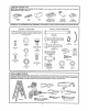
mi ................................ , CARTON CHECK ......... _ 1,1,1 ii nl SEARS has packaged your GARAGE DOOR OPENER illustrated below and on Page 22. Rag Grease Cover SEPARATE ii, ii nnll u,i ,i i, lul,, u¸ i ul ii ii i,! i i,i, LIST ALL HARDWARE ASSEMBLY in two cartons Lighl Lens FOR ASSEMBLY which contain Transmitters (21, exce._ 53415, 53315 & 53899 (1 only) Touch Code Tr',.
Assembly TO AVOID INSTALLATION DIFFICULTIES, STEP 1 J= = = ,=,,H DO NOT RUN THE GARAGE DOOR OPENER UNTIL INSTRUCTED Assemble = H H= ,,,, u,,,,,,,,,, , =J,,,,, Tee Rail & Attach , ,, ,,,,, ='== =,= =,,,,,,,, ,i TO DO SO.
Assembly i iiii n ,1,1, i, i, i STEP Ul AS A TEMPORARY 2 illUU,,lll ii ,uu, ,,11u11,,i null , Install Trofley 11111J,Ul i iiii ii I,,llLJ I u I STOP, INSERT A SCREWDRIVER T,oHE y%.,f_.,_ _,_ INTO HOLE IN FRONT END OF TEE RAiL AS SHOWN. asshown 1, At_ch threaded shaft to trolley with tockw_her _----_ .fr" and nuts 2.
Assembly i i iii ii, iii, ,JIJ,,llJ,lL,II I,,,,,,',, ii, STEP 4 , iiii i111 ,!l ,i,,,11,,11 i, Install Lii iii ii i, ii ,i i _11 ii1 Chain and Cable iiiiiiiiii I IIIII ii III II ii ,11,111111 Lii DO NOT REMOVE CHAIN AND CABLE FROM CARTON.
Assembly Hit I i, ,,i I III I ,I, I STEP 5 , ,, Loosen , Lock H,,"H IIIlllll II I Tighten I I="= HI , the Chain ,I,,H,, , H,,I and Cable .................................. CAUTION: Tighten Keep the chain from twisting turned. as nuts are PROCEDURE: Thread the outer nut toward troltey as shown. (Loosen inner nut first, if necessary.) Tension is correct when the chain is approximately 1t2" above the base of the Tee rail, midway between puIley bracket and chassis.
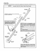
installation i,! ,i ii, iiii i, ,i,,i i, iiii1,11 i i i Position STEP 1 i , ii iiii...:: ....... iii and Instafl Header iiii L ii iiiiiii ,11 iiiii Bracket installation procedures vary according to garage door types. Follow only those instructions which apply to your door as tllustratedo i i iii i IL iii i .... := THE HEADER BRACKET MUST BE RIGIDLY FASTENED TO THE HEADER WALL. REINFORCE THE WALL WiTH 2x4 IF NECESSARY.
|n3tallation .... ii H i ml ,i ii ill ii STEP , _ ,,, 2 ,, ............. Attach , i! i i nl Tee Rail to Header I,,,IL ,i,n i,,,i,i, Bracket PROCEDURE: Position opener chassis on garage floor below the header bracket, Use packin 3 matedaI base to protect cover° NOTE: To enable the Tee rail to clear sectional door springs, it may be necessary to lift the chassis onto a temporary support, CAUTION: Chassis must either be secured to support or held firmly In place by another person.
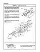
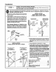
In.otallation .,,,,,,, , STEP THE OPENER CHASSIS 4 i ii ,11,1,! Hang ,11 Opener MUST BE SECURELY FASTENED i,, N, i1,, , ,,,, i ,,,,, Chassis TO A STRUCTURAL SUPPORT OF GARAGE. Three representative installations are shown. Yours may be different. Hanging brackets should be angled (Fig.l) or crossed (Fig.2) to provide rigid support, On finished ceilings (Fig.3), attach a sturdy metal bracket (not supplied) to ceiling joists before installing opener.
installation i, u,,,, i,,,. i, ,u i STEP 6 Install Waft Push Button i i i, i, ii ii ,,11 nl, liH,m LOCATE WALL PUSH BUTTON (OR ANY ADDITIONAL PUSH BUTTONS) WHERE THE GARAGE DOOR IS VISIBLE, AWAY FROM DOOR AND DOOR HARDWARE AND OUT OF THE REACH OF CHILDREN, " SERIOUS PERSONAL INJURY FROM A MOVING GARAGE DOOR MAY RESULT FROM MISUSE OF THE OPENER.
]nstaliation ILLII II I II ,_l!l,, I STEP 7 ...............ii INSTALLING ll,, ill II,I, I,, Install i I,,,, I I Ill Light and Lens ,, i , i,i ,i ,,i LIGHT: Install a 75 watt maximun light bulb in socket as shown° The light will turn on and remafn lit for 4-1/2 minutes when power is connected,, After 4d12 minutes it will turn off_ If light bulb burns out prematurely due to vibration, replace with s bulb specifically packaged for "Garage Door Openers".
Installation H i,ill nl STEP 9 i i i ill ii m,ll,iHii iH, i nl i!................ Instau Door Bracket Follow instructions TO PREVENT DAMAGE TO LIGHTWEIGHT PANELS), ALWAYS REINFORCE THE INSIDE 2x4 BOARDS OR ANGLE IRON. ,,, , rl, ill,, it i i,u,lll and Plate which apply to your door type as illustrated below. AND METAL GARAGE DOORS (OR ONES WtTH GLASS OF DOOR--BOTH VERT1C..ALLY AND HORIZONTALLY--WITH The horizontal brace should be at least 6 feet long.
nstallation ....................... ,,,., STEP 10 Connect Door Follow those only H,, ,,, Arm sure garage door is closed trolley back to the center which apply ii i,, i,,, SECTIONAL Make outer u,,..., ,,, DOOR , to your door , , i .,.,,, i, . type° ,m H,,,, ,,, ,t , , i , INSTALLATION tighL Pull the emergency release handle to disconnect of inner trolley as shown in Figures A, B and C. FIG A: Fasten straight door arm section to outer trolley with a clevis pin.
Adjustment =u ,1, ,u.,imu. 1, ,,,,,1 i i, STEP 1 ulul AdjustUP , _LL,,II, IIII II and DOWN ' ,,,", Limits ........... • i i, Ji, Limil LIMIT ADJUSTMENT settings regulate the points at which the door will stop when mowng up or down. Adjustment NOTE: Door STOPS in the UP direction if anything interferes with door travel. Door REVERSES in the DOWN direction if anything interferes with the door travel (including binding or unbalanced doors).
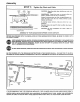
Adjustment .......... irll STEP 3 ii ............................... TestSafetyReverse System ii IIIIIL i ii THE SAFETY REVERSE SYSTEM TEST IS IMPORTANT. GARAGE DOOR MUST REVERSE ON CONTACT WITH A ONE INCH OBSTACLE PLACED ON THE FLOOR. FAILURE TO PROPERLY ADJUST OPENER MAY RESULT IN SERIOUS PERSONAL INJURY FROM A CLOSING GARAGE DOOR. REPEAT TEST AT LEAST FOUR TIMES A YEAR AND ADJUST AS NEEDED. PROCEDURE: Place a 1-inch obstacle on the floor under the garage door° Operate door in DOWN direction.
Radio Controls EC.C. rules prohibit adjustments to or modification code setting and replacing the transmitter battery Manufactured under of receiver and transmitter THERE ARE NQ OTHER ! or more of the fol_owlng U.S.
!taving a Problem? Review SITUATION PROBABLE i,,N i,ii ii i Pages 2 and CAUSE 3 Before Proceeding & SOLUTION i OPENER DOESN'T OPERATE FROM EITHER THE WALL PUSH BUTTON OR TRANSMITTER 1 Have you disengaged 2 all door tocks? Review Step 8, page 14r Does the opener have electric power? Plug a tamp into the outiet. If it doesn't light, check fuse box or circuit breaker (Some outlets are controlled by a wail switch.
Having a Problem? (continued) SITUATION ,,, i PROBABLE i i ,i i , I,H,m Ill ,.,.,I,,, DOOR REVERSES FOR NO APPARENT REASON CAUSE ,..,,m & SOLUTION . , I, .., I 1 Is something obstructing the door? Pull red emergency reteas handle Operate door manuafly If it is unbalanced or binding, call a garage door serviceman _o correct the problem. 2. Clear any ice or snow from garage floor area where garage 3.
Repair Parts RAIL ASSEMBLY PARTS LIST 5 KEY NO. 1 2 3 4 5 6 7 6 INSTALLATION PARTS PART NO,, DESCRIPTION 1A995 41B3244 4tB3243 2B313 183B93 4IB2616 4tA3473 Master link kit Outer trolley Inner trolley Tee rail-center section Tee rail-end section (each) Cable pulley bracket assy Chain and cabte NOT SHOWN 41A3534 Rail assy hardware kit (includes hardware illustrated on page 5) LIST 5 KEY NO. PART NO.