Best /CRI1 FTSMRN Owners Manual \ o o Garage Door Opener Model 139.53626SR - I/2HP Model 139.53515SR - I/2HP FASTEN THIS MANUAL NEAR THE GARAGE DOOR AFTER INSTALLATION. PERIODIC CHECKS OF THE OPENER ARE REQUIRED TO INSURE SATISFACTORY OPERATION. FOR RESIDENTIAL USE ONLY. CAUTION PLEASE READ THIS MANUAL CAREFULLY CONTENTS Safety Rules .................. Operation of Your Opener ....... Maintenance Schedule ... Features of Your Opener.. Specifications ........... Accessories ............
Start By Reading These Important Safety Rules THIS SAFETY ALERT SYMBOL MEANS CAUTION -- PERSONAL SAFETY OR PROPERTY DAMAGE INSTRUCTION, READ THESE INSTRUCTIONS CAREFULLY. THIS GARAGE DOOR OPENER IS DESIGNED AND TESTED TO OFFER REASONABLY SAFE SERVICE PROVIDED IT IS INSTALLED AND OPERATED IN STRICT ACCORDANCE WITH THE FOLLOWING SAFETY INSTRUCTIONS. FAILURE TO COMPLY WITH THE FOLLOWING INSTRUCTIONS PERSONAL INJURY OR PROPERTY DAMAGE.
Operation of Your Opener CAUTION • BEFORE YOU PROCEED, PLEASE READ THE SAFETY RULES ON PAGE 2 AND OPERATING INSTRUCTIONS ON THIS PAGE CAREFULLY. • TO AVOID DIFFICULTY DURING INSTALLATION, DO NOT RUN OPENER UNTIL INSTRUCTED TO DO SO. • • DO NOT PERMIT CHILDREN TO PLAY IN DOOR AREA. OPERATE ONLY WHEN OPENER IS PROPERLY ADJUSTED AND UNOBSTRUCTED. THE DOOR IS VISIBLE AND USING THE OPENER WHEN OPENER Your opener can be activated by any of the following devices: 1. If open, the door will close.
FEATURES OF YOUR OPENER 1. Motor: Permanently lubricated with automatic reset. 2. Opener Lights: Turn on and off automatically with 41/z minute illumination for your safety and convenience. Provide constant light when Light Feature is activated. 7. 3-Function Transmitter: Has three push buttons. Each button can activate one or more remote control devices. Opener is factory preset to activate when LARGE push button on transmitter is pressed. 3. Safety System: Independent up and down force adjustment.
CARTON CHECK LIST SEARS has packaged your GARAGE DOOR OPENER In two cartons which contain all the parts and hardware Illustrated below and on Page 22. Co_r Rail Light 3 Function "i'ar_mitter Grease Lens (2) Mode_139_53626(1) Modd139.53515 (2) SEPARATE ALL HARDWARE ASSEMBLY l_readed FOR ASSEMBLY AND INSTALLATION PROCEDURES INSTALLATION HARDWARE HARDWARE Clevis Pin Trolley Rod 11) 5/16" x 2_/4" 5/16--18 x 2-1/2" _2) (_ Lock'washer 5/16" (4) Washered Screw Master Link AS SHOWN BELOW.
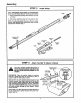
Assembly TO AVOID INSTALLATION DIFFICULTIES, STEP 1 DO NOT RUN THE GARAGE DOOR OPENER UNTIL INSTRUCTED Assemble Tee Rail & Attach Cable TO DO SO. Pulley Bracket TEE RAIL BACK (TO CHASSIS) Tee Rail (End Section) CAUTION: Do not _ghten the lock nuts until bolt necks rre seated in square holes. 1/4" Lodx Nut TeeRail Br_. (CemerSec_on) The end section,, of the rail MUST be connected to the center section from the direction shown in the illustration.
Assembly STEP 2 InstallTrolley AS A TEMPORARY STOP, INSERT A SCREWDRIVER INTO HOLE IN FRONT END OF TEE RAIL AS SHOWN. 1. Attach threaded as shown. sha_ to trolley with Iockwasher 2. Slide trolley assembly and nuts along rail to screwdriver stop, NOTE: If trolley hits against the nut on Tee rail, center section was attached from wrong side and must be repositioned. Review Step 1. Temporary Stop Screwdriver Cuter Nut f LockWasher Inner Nut 5/16" 5/16" \ Trolley STEP 3 Attach Tee Rail To Opener
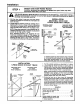
Assembly STEP 4 Install Chain and Cable DO NOT REMOVE CHAIN AND CABLE FROM CARTON. install Chain Detach cable from side of carton. Remove master links from coin envelope.. B Opener In This Direc1_n MASTER LINK PROCEDURE: Insert pins of master link bar through cable loop and hole in front end of trolley (A) as shown. Push cap over pins and onto notches. Slide clipon spring over cap and onto pin notches until pins are locked in place. Caution: Keep the chain taut while installing prevent kinking.
Assembly STEP 5 Tighten Lock Tighten 13ghten the Chain CAUTION: and Cable Keep the chain from twisting as nuts ere turned. PROCEDURE: Thread the inner nut on the trolley in the direction shown. Tension is correct when the chain is approximately 1/2" above the base of the Tee rail midway between the cable pulley bracket and the opener. Troll_ To maintain proper tension, tighten outer nut as shown. Sprocket noise can result if chain is either too loose or too tight.
Installation Position and Install Header Bracket STEP 1 Installation procedures are determined instructions which refer to your door. by garage door typeS. Follow only those THE HEADER BRACKET MUST BE RIGIDLY FASTENED TO THE HEADER WALL. REINFORCE THE WALL WITH A 2x4 IF NECESSARY. FAILURE TO COMPLY MAY RESULT IN IMPROPER OPERATION OF SAFETY REVERSE SYSTEM (SEE PAGE 18). INSTALLATION SECTIONAL DOOR AND 1-PIECE DOOR WITH TRACK 1.
Installation STEP 2 Attach Tee Rail to Header Bracket PROCEDURE: Position opener chassis on garage floor below the header bracket. Use packing material base to protect cover. NOTE: To enable the Tee rail to clear sectional door springs, it may be necessary to lift the chassis onto a temporary support. Header Bracket Cle_s Pin 5/16"x2-3/4" CAUTION: Chassis must either be eecured to support or held firmly in place by another person. Raise the Tee rail until pulley and header brackets come together.
Installation STEP 4 THE OPENER CHASSIS Hang Opener Chassis MUST BE SECURELY FASTENED TO A STRUCTURAL SUPPORT OF GARAGE. Three representative Installations are shown. Yours may be different. Hanging brackets should be angled (Fig.l) or crossed (Fig.2) to provide rigid support, On finished ceUings (Fig.3), attach a sturdy metal bracket (not supplied) to ceiling joists before installing opener. PROCEDURE: On EACH side of the opener measure the distance from chassis to the structural supports.
Installation STEP 6 In,t . Wall Control LOCATE WALL CONTROL (OR ANY ADDITIONAL PUSH BUTTONS) WHERE GARAGE DOOR IS VISIBLE, AWAY FROM DOOR AND DOOR HARDWARE AND OUT OF REACH OF CHILDREN. SERIOUS PERSONAL INJURY FROM A MOVING GARAGE DOOR MAY RESULT FROM MISUSE OF OPENER. DO NOT ALLOW CHILDREN TO OPERATE WALL PUSH BUTTON(S) OR TRANSMITTER. FASTEN CAUTION LABEL ON THE WALL NEAR THE WALL CONTROL OPERATING PROCEDURES.
Installation STEP 7 Install Lights and Lenses Make sure antenna wire is bent down before installing lights and lenses. 75 Watt Max. Install a 75 Watt maximum light bulb in each socket as shown. The lights will turn on and remain lit for 4-1/2 minutes when power i-sconnected. After 4-1/2 minutes they will turn off. For constant light, press the Light push button on the Wall Control.
Installation STEP 9 Install Door Bracket and Plate Follow instructions which apply to your door type as Illustrated below. ALWAYS RE NFORCE THE NSIDE OF DOOR--BOTH VERTICALLY AND HOR ZONTALLY--W TH 2x4 TO PREVENT TO LIGHTWEIGHT AND METAL GARAGE DOORS OR ONES WITH GLASS PANELS BOARDS OR DAMAGE ANGLE IRON. The horizontal brace should be st least 6 feet long. The vertical brace should cover height of top panel.
Installation STEP 10 Connect Door Arm to Trolley Follow only those instructions SECTIONAL DOOR which apply to your door type. INSTALLATION Make sure garage door is closed tight. Pull the emergency release handle to disconnect the trolley. Manually move outer trolley back to the center of inner trolley as shown in Figures A, B and C. FIG A: Fasten straight door arm section FIG B: Bring arm sections together, Find FIG C: If holes in curved arm are ABOVE to outer trolley with a clevis pin.
Adjustment STEP 1 Adjust UP and DOWN LIMIT ADJUSTMENT settings (left side panel) regulate the paints at which the door will stop when moving up or down, NOTE: Door STOPS in the UP direction if anything interferes with door travel. Door REVERSES in the DOWN direction if anything interferes with the door travel (including binding or unbalanced doors). PROCEDURE: Press Wall Control push button or transmitter. Run opener through a COMPLETE TRAVEL CYCLE.
Adjustment STEP 3 Test Safety Reverse System THE SAFETY REVERSE SYSTEM TEST IS IMPORTANT. GARAGE DOOR MUST REVERSE ON CONTACT WITH A ONE INCH OBSTACLE PLACED ON THE FLOOR. FAILURE TO PROPERLY ADJUST OPENER MAY RESULT IN SERIOUS PERSONAL INJURY FROM A CLOSING GARAGE DOOR. REPEAT TEST AT LEAST FOUR TIMES A YEAR AND ADJUST AS NEEDED. PROCEDURE: Place a 1-inch obstacle on the floor under the garage door. Operate door in DOWN direction. The dOor MUST reverse on the obstruction.
Radio Controls EC.C. rules prohibit adjustments to or modification of receiver and transmitter circuitry except for changing the code setting and replacing Manufactured the transmitter battery. THERE ARE NO OTHER under 1 or more of the following U.S. patents: RF.29,525; 4,037.201; 4,750.n8; USER SERVICEABLE 4,806,g30. PARTS. Other patents pending.
Having a Problem? Review Pages 2 end 3 Before Proceeding SITUATION PROBABLE CAUSE & SOLUTION OPENER DOESN'T OPERATE FROM WALL CONTROL OR TRANSMITTER 1. Have you disengaged all door locks? Review Step 8, page 14. 2. Does the opener have electric power? Plug a lamp into the outlet. If it doesn't light, check fuse box or circuit breaker. (Some outlets are controlled by a wall switch.) 3. Repeated operation may have tripped the overload protector in the motor. Wait 15 minutes. Try again. 4.
Having a Problem? (Continued) SITUATION PROBABLE CAUSE & SOLUTION DOOR REVERSES FOR NO APPARENT REASON 1. Is something obstructing the door? Pull red emergency release handle. Operate door manually. If it is unbalanced or binding, call a garage door serviceman to correct the problem. 2. Clear any ice or snow from garage floor area where garage door closes. 3. Review the Force Adjustment Chart on page 17. REPEAT SAFETY REVERSE TEST after adjustment is complete. 4.
Repair Parts RAIL ASSEMBLY PARTS LIST 3 KEY NO. 1 2 3 4 5 6 7 INSTALLATION KEY NO. PART NO. 1 2 3 41A3472 10A14 41A3476 4 5 6 7 29C 128 41A2828 217A209 41A2829 8 9 10 11 12 12B374 12B380 178B35 178B34 12B350 41A3535 114A 1276 PARTS PART NO. DESCRIPTION 1A995 41 B3243 41 B3244 1B3117 183Bl10 41B2616 41A3473 Master link kit Inner trolley wlthreadud rod Outer trolley Tee rail-center section Tee rail-end section (each) Cable pulley bracket assy.
Repair Parts Chassis Assembly Parts List I 19 18 9 5 15 17 14 16 (Oown) Brown Contact UMIT SWITCH ASSY, \ Grey Wire Drive Gear .Contact KEY NO. PART NO. 1 2 31C290 41A2827 3 41A2817 4 5 6 41B2991 41C2725 41A3493 KEY NO. DESCRIPTION Sprocket cover Gear and sprocket assy, Complete with: Swing washer Thrust washer Retaining ring Bearing plato Roll pins (2) Ddve gear Worm gear Helical gear w/retainer Grease Drive/worm gear kit with grease & roll pins (2) Line cord Wire harness assy.
Bes / CRRFTSMRN® Owners Manual HOW TO ORDER REPAIR PARTS Now that you have purchased your Sears Garage Door Opener, should a need ever exist for repair parts or service, simply contact any Sears Service Center and most Sears Roebuck and Co. stores. Be sure to provide all pertinent facts when you call or visit. The MODEL NUMBER is printed on a label located on the right side panel of the garage door opener. Garage All parts listed may be ordered from any service center and most Sears stores.