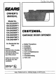
SEARS OWNER'S MANUAL Model No. 139.53225SRT1 139.53325SRT1 139.53425SRT1 139.53628SRT1 139.53629SRT1 139.53635SRT1 139.53637SRT1 139.53824SRT1 For Residential Use Only CRRFTSMRN® GARAGE DOOR OPENER • Safety Precautions • Assembly • Installation Caution: Read and follow all safety rules and operating Instructions before first use of thls product. Fasten the manual near • Adjustment • Care and Maintenance • Operation • Troubleshooting • Parts List the garage door after Installation.
Contents Page A review of safety alert symbols................................. 2 You'll need tools.......................................................... 3 Safety information regarding garage door locks and rope_ ............=,..... °o,, .. °.,, o...o, _°o ....... balance........... .................... ..... .............. ..° .......... Page Installthe light and lens ................................................. 1 Attach emergency release rope and handle .................
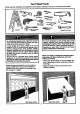
You'll Need Tools During assembly, installation and adjustment of the opener, instructionswill call for hand tools shown below. Level Hack_ _) A_usta_e End Wrench An unbalanced garage door might not reverse when required and someone under the door could be seriously injured or killed. If your garage door binds, sticks or is out of balance, call for professional garage door service.
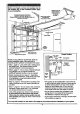
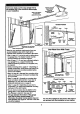
Before you begin, survey your garageareato see whether any of the conditions belowapply to your Installation. Horizontaland vedlsal reinfo(cement Is needed for I_htweight garagedoors (fiberglass,steel, aluminum, doorwith g_asspanels,etc.). See page 24 fordeta_. RNISHED CEIUNG Supportbracket& fasteninghardware Is required. See page17. Slack in ChainTension ls NomadWben Garage Doorls CIo_',ed Header Wall Safety Reversing Sensor- Closed Position • Safety ReversingSensor .
Beforeyou begin,surveyyourgarageareato seewhetherany of the conditions below apply FINISHED CEIUNG S.p_ttnck_ & fastening hardware Is required. See page 17. to your installation. Slack In chain tension h;nom_ when garage doorisclosed. Header WJ Closed Position Cable Pulley BrscketCable Accesscucx Header Bracket Trolley T-rail O Garage - Door 3ap betweenfloorand bottomRevendngSensor of doormustnot e_ceed I/4".
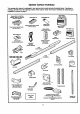
Opener Carton Inventory Your garage door opener is packaged in two cartons which contain all parts illustrated below, ff anything is missing, carefully check the packing material. Parts may be "stuck" in the foam. Hardware for assembly and installation is shown on page 7.
Separate ell hardware from the packages In the rail carton and the opener carton, as shown below, for the assembly and installation procedures. Assembly Hardware WasheredScrew 5/16" - 18 x 1/2" (2) (mountedIn ogene_ Hex Screw 5/16" - 18 x 7/8" (3) Nut 5/16" - 18 (5) Ca_age SCb 1/4" - 20 x 1/2" (4) © Trolley"_reeded Shaft(1) Master[.
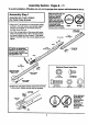
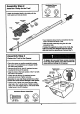
Assembly Section: Pages 8 - 11 To avoid Installation difficulties, do not mn the garage door opener until Instructed to do so. Assembly Step I Assemble the T-rail & Attach the Cable Pulley Bracket • Align the 3 T-rail sections on a flat surface exactly as shown. The end sections are identical. Make sure the "arrow label" on the center section is pointing toward the door. Make sure bolt necks are seated In the square holes and rails are aligned beforeyou tighten lock nuts. (See right and wrong views).
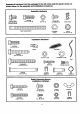
Assembly Step 2 Install the Trolley Hardware Shown Actual Size I I on the T-rail ©© • Attach the threaded shaft to the trolley with the lock washer and nuts as shown. LockWssher 5/16" Nut 5/16" - 18 Tro_y LockWasher 5116" OutorNut T_ Thm_l Shaft kmer Nut 5/16" Tro,ey Tempormy Sto_ Screwdriver • As a temporary stop, insert e screwdriver into the hole in the front end of the T-rail. • Slide the Volley assembly along the rail to the screwdriver stop.
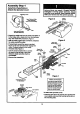
Assembly Step 4 Install the Chain/Cable & Attach the Sprocket Cover entangle¢l In moving opener sprockeL Attach sprocket cover eecurely. Never operate oPener I)i_per_ng Carton Figure 2 op.,_ sprocket • Detach the cable loop from the carton and fasten it to the trolley with a master link from the hardware bag. See master link procedure, Figure 1. Figure 3 • W'dhthe trolley against the screwdriver, dispense the cable around the pulley. • Proceed back around the opener sprocket, Figure 2.
Assembly Step 5 Tighten the Chain & Cable Outer Nut Lock W_hw Inner Nul • Spin the inner nut and lock washer down the threaded shaft, away from the trolley. • To tighten the chain, tum outer nut in the direction shown. As yon tum the not, keep the chain from twisting. 0 • When the chain is approximately 1/2' above the base of the T-rail at its midpoint, re-tightso the inner nut to secure the adjustment. @ Sprocket noise can result if chain is either too loose or too Ught.
Installation Section: Pages 12- 27 Installation Step I Determine Header Bracket Location Installation procedures vary according to garage door types. Follow the instructions which apply to your door. a structural support on the header wall or ceiling, the safety reverse system may not work properly (see page 30). The door might not reverse when required, and could cause serious Injury or death. The garage door springs, cables, pulleys, brackets and their hardware are under extreme tension.
Read the Safety instructions on page 12. They also apply to doors without tracks. HeaderWall 2x4 • Close the door and mark the inside vertical cantedine of your garage door. Extend the line onto the header wall above door. If headroom clearance is minimal, you can install the header bracket on the ceiling. See page 14.
Install the Header Bracket Installation Step 2 You can attach the header bracket either to the wall above the garage door, or to the calling. Follow the Instructions which will work best for your particular requirements. I Fasten the Header Bracket to the Wall • Center the bracket on the vertical guideline with the bottom edge of the bracket on the horizontal line as shown (with the arrow pointing toward the ceiling).
Attach the T-railStep to the 3Header Bracket Installation I • Position the 6pener on the garage floor below the header bracket. Use packing material as a protect'we base. // /'-,/// / / // -- HeaderWall If the door spring is In the way you'll need help. Have someone hold the opener securely on a temporary support to allow the T-rail to clear the spring. Header Bracket // / / .// / / Cable • Position the cable pulley bracket against the header bracket.
Installation Step 4 Position the Opener Follow instructions type as Inustbrated. which apply to your door A 2x4 laid flat is convenient for setting an ideal door-to-T-rail distance. • Raise the opener onto a stepladder. T-rail You will need help at this point ff the ladder Is not tall enough. • Open the door all the way and place a 2x4 laid fiat on the top sec/Jon beneath the T-rail.
Installation Step 5 Hang the Opener Two representatlve Installations are shown. Yours may be dlfferent. Hanging brackets should be angled, Figure 1, to provide rigid support. On finished ceilings, Figure 2, attach a sturdy metal bracket to structural supports before installing the opener. The bracket and fastening hardware are not suppfied. See accessory page 38. Figure I Structund • Measure the distance from each side of the opener to the structural support.
I Installation Step 6 Install the Wall Control Children operating or playing with a garage door opener can Injure themselves or others. The garage door could close end cause serious Injury or death. Install the Wall Control (or any additional push buttons) out of the reach of children and away from all moving parts of the door and door hardware, but where the garage door is visible. Do not allow children to operate the push button(a) or the remote control(s).
I Installation Step 7 Install the Light and the Lens Install the Ilghta • Install a 75 watt maximum light bulb in the socket. The light Jill turn ON and remain lit for approximately 4-1/2 minutes when power is connected. Then the light will turn OFF. LensGuide • If the bulb bums out prematurely due to vibration, replace it with a standard neck "Garage Door Opener" bulb.
Installation Step 9 Electrical i Requirements [ I To prevent electrocution or fire, Installation end wiring must be In compliance with local electrical and building codes. To reduce the risk of electric shock, your garage door opener has a grounding type plug with a third grounding pin.
Safety Reversing System Information you'll need before you begin the Inatallation of the safety reversing sensor. The safety reversing sensor mustbe connected and aligned correctly before the garage door opener will move In the down direction. This Is a required safety device and cannot be disabled. Without a properly working safety reversing sensor, persons (particularly children) could be Injured or killed by a closing garage door. Read and follow all Instructions.
Installation Step 10 Install the Safety Reversing I I Sensor Figure 2" Figures 2 and 3 show assembly of brackets and 'C" wrap based on the recommended installation of the sensors as shown on page 21. Mour_ngBracket WithSquareHokm However, Figures 4 and 5 are variations which may fit your installation requirements better. Make sure the wraps and brackets are aligned so the sensors will face each other across the garage door.
• Ce_ereachsensorunitin a "C' wrap with lenses pointing toward each other across the door (see Figure 6). Figure 6 • Secure sensors with the hmdware shown. Finger tighten the wing nut on the receiving eye to al ow for final adjustment. Securely tighten the sending eye wing nut. • Run the wires from both sensors to the opener. Use insulated staples to secure wire to wall and ceiling. • Strip 1/4" of insulation from each set of wires.
Installation Step 11 Fasten Door Bracket Follow instructions which apply to your door type as illustrated below or on page 25. A horizontal brace should be long enough to be secured to 2 vertical supports. A vertical brace should cover the height of the top panel. The IllustrstJon shows one piece of angle iron as the horizontal brace. For the vertk!al brace, 2 pieces of angle iron are used to create a "U"-shaped support.
Please read and comply with the wamings and reinforcement InstrucUons on page 24. They apply to one-piece doors also. Header Wall Header Brac_t Bracket Placement of Door Bracket Vertical Garage Door Door Bracket, ofDoor 5/16"-18x2-1/2 • Center the bracket on the top of the door, in line with the header bracket as shown. Mark holes. Hardware Shown Actual Size • Ddll 5/16" pilot holes and fasten the door bracket with hardware supplied.
Installation Step 12 Connect Door Arm to Trolley Follow instructions which apply to your door type as Illustrated below and on page 27. Make sure garage door is fully closed. Pull the emergency release handle to disconnect the outer trolley from the Inner trolley. Slide the outer trolley back (away from the door) about 2" as shown in Figures 1, 2 and 3. Figure 1: Figure 2: Fasten straight door arm section to outer trolley with a clevis pin. Secure the connection with a ring fastener.
Assemblethe DoorArm: Door Bracket • Fasten the straight and curved door arm sections together to the longest possible length (with a 2 or 3 hole overlap). ClevtsP_ • With the door closed, connect the straight door arm section to the door bracket with a clevis pin. Str_dght Ann • Secure with a ring fastener. 5/16"-18x9'/8 _-_ Cun/ed Do_xAnn On one-piece doors, before connecting the door arm to bhetrolley the travel limitsmust be adjusted.
Adjustment Section: Pages 28 - 30 Adjustment Step 1 Adjust the UP and DOWN Limits Do not make any limit adjustments unUI the safety reversing sensors are completely Installed. Umit adjustment settings regulate the points at which the door will stopwhen moving up or down. The door will stop in the up direction if anything interferes with door travel. The door will reverse in the down direction if anything interferes with the door travel (including binding or unbalanced doom).
I Adjustment Step 2 Adjust the Force I the prop_on Force adjustment controls are located on the beck panel of the opener. Force adjustment set'rings regulate the amount of power required to open end close the door. I The door will stop in the up direction if anything interferes with its travel. The door will reverse in the down direction if anything interferes with its travel (including binding or unbalanced doors). of the safety reverse d.
Adjustment Step 3 Test Reversing The Safety Sensor • Press the remote control push button to open the door. • Place the opener carton in the path of the door. I • Press the remote control push button to close the door. The door will not move more than an inch, and the opener light will flash. I--7oF--] Professional service Is required If the opener closes the door when the safety reversing sensor Is obstructed.
IMPORTANT SAFETY INSTRUCTIONS To reduce the risk of severe injury or death to persons: 1. READ AND FOLLOW ALL INSTRUCTIONS. 2. Do not permit children either to operate or to play with the opener. Keep remote control In s location Inaccessible to children. 3. Operate opener only when the door Is In full view end froe from any obstruction. Keep the door In sight until it Is completely closed. NO ONE SHOULD CROSS THE PATH OF THE MOVING DOOR. 4. Check safety reversal system monthly. See page 30.
Operation of Your Opener Aotlva_ the opener v_lh any of the fullowing: 1. The Remote Control • 3-FuncUon and C_mpact: Hold large push button down until the door starts to move. Weak or broken springs could allow an open door to fall (either rapidly or unexpectedly), resulting in serious Injury, death or property damage. If possible, use the emergency release rope end handle on/y when the door Is fully closed. • Single function: Hold push button until the door starts to move. 2. The Wall Control.
Receiver and Remote Control Programming To comply with FCC rules, adjustment or modificationsof this receiver and/or transmitter are prohibited,except for changing the code setting or replacing the battery, THERE ARE NO o'n.IER USER SERVICEABLE PARTS. Models with 3-function remote controls: The remote control(s) has been factory set to operate with the large push button. However, you can use either of the two small buttons, if you prefer.
Having a Problem? Situation Probable Cause and Solution The opener doesnl operate from either the Wall Control or the remote control: 1. Does the opener have electd.cpower? Plug.a lamp into the outlei, ff it doesn't light, check the fuse box or the drcuit breaker. (Some outlets are controlled by a wall switch.) 2. Have you disabled all door locks? Review installationinstructionwarnings on Page 11. 3. Is there a build-up of ice or snow under the door? The door may be frozen to the ground.
Having a Problem? (conUnued) Situation Probable Cause & Solution The door opens but won l close: 1. ff the opener lights blink, check the safety reversing sensor. See page 23. 2. If the opener lights do not blink and it is a new installation, check the down force. See Adjustment Step 2, page 29. For an existing installation, see below. Repeat the safety reverse test after the adjustment The door reversas for no apparent reason and opener Ilghte don _tblink: Is complete. 1.
Repair Parts Rail Assembly Parts 5 KEY NO. PART NO. 1 2 3 4 5 6 7 1A995 41A3489 1B3117 183Bl10 83A4 41A3473 41B2616 41 A3534 KEY NO. 1 2 3 4 PART NO.
Repair Parts Opener Assembly Parts (_,,m u.rr swn_ Bro_ c=t_ °.:"-" CenterLimit contact KEY NO. 4 5 6 7 8 9 10 PART NO. 14 J_sE.e,v (Up) c
Accessories Sears offers many useful accessories for your garage door opener. They are Illustrated below with Sears model numbers and descriptions. 53702 j 53703 Emergency KeyReieese: 53759 access door. Required for a garage with NO Outdoor Key Switch: _'_ _ 53773 Opens the garage door automatically from outside when remote control is not handy.
Index Access Door/Outside Key Release Accessory ............................................................................................... 4, 5 Chain Tension .............................................................................................................................................. 4, 5, 11 Electrical Safety Warnings ........................................................................................................................
CRAFTSMAN® OWNER'S MANUAL GARAGE DOOR OPENER For the repair or replacement parts you need Call 7 am -7 pm, 7 days a week 1-800-366-PART Model No. 139.53225SRT1 139.53325SRT1 139.53425SRT1 139.53628SRT1 139.53629SRT1 139.53635SRT1 139.53637SRT1 139.