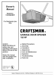
Owner's Manual Model No. 139.53663SRT For Residential Use Only I:RRFTSMRN+ GARAGE DOOR OPENER 1/2 HP Caution: Read and follow all safety rules and operating instructions before first use of this product. Fasten the manual near the garage door after installation. Complies with UL 325 /11 regulations effective January !, 1993 • Safety Precautions • Assembly • Installation • Adjustment • Care and Maintenance • Operation • Troubleshooting • Parts List _ Sears, Roebuck and Co.
Contents Safety alert symbol review ............................................ Safety information, precautions, 2 tools .......................... 3 Complete the safety reversing sensor installation.....22 Install the lights and lens .......................................... 23 Testing your garage door for binding & balance .......... 3 Attach the emergency release rope and handle ......... 23 Carton inventory ...........................................................
Safety Information and Precautions; An unbalanced garage door might not re verse when requiredand someone underthe door couldbe seriously injuredor killed. If yourgaragedoor binds,sticksor is out of balance,call for professionalgaragedoor service.Garagedoors,door springs,cables,pulleys,brackets,and theirhardwareare under extremetension and can cause seriousinjury or death. Do not try to loosen, move or adjust them yourself! Ropes left on a garage door could cause someone to become entangled and killed.
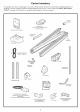
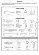
Carton Inventory Your garage door opener is packaged in one carton which contains the power unit and all parts illustrated below. If anything is missing, carefidly check the packing material. Parts may be "stuck" in the foaln. KEEP THE FOAM INTACT (see page i0). Hardware for assembly and installation is shown on page 5. Coupling _ SECURITY+ Three-Function Remote Control with Visor Clip (2) _ Sprocket Premium Control Console Rait Support .
Hardware Separate all hardware from the assembly and installation the packages procedures.
SECTIONAL Door Installation Before you begin, survey your garage area to see whether any of the conditions below apply to your installation. FINISHED CEILING Support bracket & fastening hardware is required See page 20. Horizontal and vertical reinforcement is needed for lightweight garage doors (fiberglass, steel, aluminum, door with glass panels, etc.). See page 24 for details i \,,,Header Wall Extension Spring OR Torsion Spring Access Door Door O Safety Reversing Sensor Ftoor must be level acro
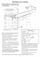
ONE-PIECE Door Installation Before you begin, survey your garage area to see whether any of the conditions below apply to your FINISHED CEILING Support bracket & fastening hardware is required. See page 20. installation. Header Wall One-Piece Door without Track Closed Position Rail Bracket Access Door Rail Assembly Header Bracket Trolley Door Bracket O Emergency Release Garage Door Safety Reversing Sensor Gap between floor and bottom of door must not exceed 1/4".
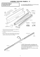
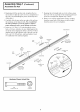
ASSEMBLY I SECTION: I Assembly Step 1 Assemble the Rail To avoid installation difficulties, do not run the garage door opener until instructed to do so. Straight DoorArm Rail Support Braces PAGES 8 - 11 Extend End RaiIs Outward Remove Cardboard Center Rail -- Trolley Rail Assembly Hardware Bag Rail Assembly Carton Remove Cardboard Packing Packing Rack Chassis Assembly Hardware Bag I / / _ Extend End Raits Outward 1.
Assembly Assemble Step 1 (Continued) the Rail 4. Begim_ing with the sprocket end, straighten the two rail sections so that the screw rod is in a straight line at the joint. (Avoid handling the joints, which may have sharp edges.) 7. Keeping the rail straight and on a level surface, grasp the screw rods on each side of the remaining joint and pivot into a straight line. Repeat steps 5 and 6. 8.
Assembly Step 2 Fasten the Rail To the Power Unit and Install the Trolley NOTE: To aid in assembly and installation, replace the foam packing around the power unit. Remove it after Installation Step 5. • Working on a level surface, align the rail assembly with the power unit, as shown. Rail/Power Unit Bracket Sprocket Lock Nuts 1/4"-20 • Slip the coupling over the rail sprocket. I • Slide the rail through the power unit bracket until the coupling fits securely over the power unit sprocket.
Assembly Step 3 Attach the Rail Brackets 1/4"-20 Lock Nuts Rail • Align rail brackets to end of rail assembly, as shown. • Insert two i/4"-20 x 5/8" hex screws and lock nuts. Tighten securely with a 7/16" socket. Hardware Shown Actual Size 1/4" - 20 Lock Nut 1/4" - 20 x 5/8" 1/4"-20x5/8 Hex Screws You have now finished assembling your garage door opener.
INSTALLATION Installation Determine SECTION: PAGES 12- 27 Step 1 Header Bracket Location If the header bracket is not rigidly fastened to a structural support on the header wall or ceiling, the safety reverse system may not work properly (see page30). The doormightnot reverse whenrequired,and cou/dcauseseriousinjuryor death. Installation procedures vary according to garage door _'pes. Follow the instructions which apply to your door.
ONE-PIECE Read the Safety Instructions Door Without Track on page 12. They also apply to doors without • Close the door and mark the inside vertical centerline of your garage door. Extend the line onto the header wall above door. tracks. Header Wail Vertical Centerline 2x4 If headrooln clearance is minimal, you can install the header bracket on the ceiling. See page 14.
Installation Install Step 2 the Header Bracket You can attach the header bracket either to the wall above the garage door, or to the ceiling. Follow the instructions which will work best for your particular requirements. Fastening the Header Bracket Fastening to the Wall • Center the bracket on the vertical guideline with the bottom edge of the bracket on the horizontal line as shown (with the arrow pointing toward the ceiling).
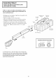
Installation Step 3 Attach the Rail to the Header Bracket • Position the opener on the garage floor below the header bracket. Use packing material as a protective base. If the door spring is in the way you'll need help. Have someone hold the opener securely on a temporary support to allow the rail to clear the spring. Header Wall • Position the rail bracket against the header bracket. • Align the bracket holes and join with a clevis pin as shown. • Insert a ring fastener to secure.
The Safety Reversing Sensor Information you'll need before you begin the installation of the safety reversing sensor The safety reversing sensor must be connected and aligned correctly before the garage door opener will move in the down direction. This is a required safety device and cannot be disabled. Without a properly working safety reversing sensor, persons (particularlychildren)couldbe injured or killed by a closing garage door.
Installation Step 4 Install the Safety Reversing Sensor (Receiving and Sending Eyes) Figure 1 Figures 1 and 2 show assembly of brackets and "C" wrap based on the recolmnended installation of the sensors on each side of the garage door as shown on page 16. However, Figures 3 and 4 are variations which may fit your installation requirelnents better. Make sure the wraps and brackets are aligned so the sensors will face each other across the garage door.
the Safety Reversing Sensor I Install Installation Step 4 (Continued) I 7. Center each sensor unit in a "C"- wrap with lenses pointing toward each other across the door (see Figure 5). 8. Secure sensors with the hardware shown. Finger tighten the wing nut on the receiving eye to allow for final adjustment. Securely tighten the sending eye wing nut. Recommended Wire Routing Figure 5 1. Using insulated staples, run the wires froln both sensors m the rail at the door header (see Figure 6).
Installation Position Step 5 the Opener Follow instructions as illustrated. which apply to your SECTIONAL A 2x4 laid flat is convenient to-rail distance. • Raise the opener for setting door type Door or ONE-PIECE an ideal Door with Track doorRail 2x4 onto a stepladder You will need help at this point enough. if the ladder is not tall Foam • Open the door all the way and place the top section beneath the rail.
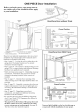
I Hang the OpenerStep 6 I Installation Two representative installations are shown. Yours may be different. Hanging brackets should be angled, Figure 1, to provide rigid snpport. On finished ceilings, Figure 2, attach a stnrdy metal bracket to strnctural supports before installing the opener. The bracket and fbstening hardware are not supplied. Figure 1 1. Measure the distance from each side of the opener to the structnral support. Supports 2. Cut both pieces of the hanging bracket to required lengths.
Installation Step 7 Install the Premium Control and Connect all Wiring Console Do not connect to live electrical wiring. Connect only to 24 Volt low voltage wires. Connection to live wires or higher v oltage may cause serious injury from shock, burn or electrocution. Locate the door control within sight of the door at a minimum height of 5 feet where small children cannot reach, and away from all mo,ing parts of the door and door hardware.
Installation Electrical Step 8 Requirements To preventelectrocutionor fire, installationand wiring mustbe in compliancewith localelectricaland building codes, To reduce the risk of electric shock, your garage door opener has a grounding type plug with a third grounding pin. This plug will only fit into a grounding type outlet.
Installation Install Step 10 the Lights and Lens "_ x_J • Install a 100 watt lnaxilmnn light bulb in each socket. The lights will turn ON and relnain lit for approxilnately 4-1/2 lninutes when power is connected. Then the lights will mm OFF. • Insert bottom lens tabs into slots on chassis and tilt towards chassis to engage top tabs, then drop down gently into place. (See ilhtstralT"om) Top Lens Slot -. • To relnove, lift lens up and gently tilt slightly outward and down, then pull out to clear bulbs.
Installation Fasten Step 12 Door Bracket Follow instructions which apply to ),our door type as illustrated below or on page 25. A horizontal brace should height of the top panel. be long enough to be secured to 2 vertical supports. A vertical The illustration shows one piece of angle iron as the horizontal brace. For the vertical are used to create a U-shaped support. The best solution is to check with your garage opener installation door reinforcement kit.
All ONE-PIECE Please read to one-piece and comply doors also. with the warnings Door Installation and reinforcement Procedure instructions on page 24.
Installation Connect Step 13 Door Arm to Trolley Follow instructions which apply to your door _pe as illustrated below and on page 27. SECTIONAL Doors Only Make sure garage door is fully closed. Pull the emergency release handle to disconnect the outer trolley from inner trolley. Slide the outer trolley back (away from the door) about 2" as shown in Figures l, 2 and 3. Figure 1: Figure • Fasten straight door arm section to outer trolley with the 5/16"xl" clevis pin.
All ONE-PIECE Assemble the Door Doors Arm: Ring Door • Fasten the straight and curved door arm sections together to the longest possible length (with a 2 or 3 hole overlap). Lock Washers Nuts 5/16"-18 5/16" • With the door closed, connect the straight door arm section to the door bracket with the 5/16"x1-1/4" Straight Arm clevis pin. Screws 5/16%18x7/8 • Secure with a ring t:astener.
ADJUSTMENT Adjustment SECTION: PAGES 28 - 30 Step 1 Adjust the UP and DOWN Limits Improperadjustmentof the travel limitswill interferewith the properoperation of the safety reverse system. The door mightnot reverseproper/ywhenrequiredand cou/d serious/yinjure or ki// someoneunder it. Test the safety reversesystemmonthly,and followingall adjustmentsto thetravel limits.See page30. Do not make any limit adjustments until the safeR" reversing sensors are completely installed.
Adjustment Step 2 Adjust the Force Too muchforce on the doorwill interferewith the proper operationof the safety reversesystem. The door might not reverseproper/ywhen requiredand cou/d serious/y injureor ki// someoneunderit. Do not increasethe force beyondthe minimumamountrequiredto closethe door. Do not use the force adjustmentsto compensatefor a bindingor sticking garagedoor.Test the safety reverse system monthly,and followingall adjustmentsto force levels.See page30.
Test the Safety Reversing I Adjustment Step 3 • Press the relnote control • Place the opener carton I Sensor push button Without a properly working safety reversing sensor, persons(particularlychildren)couldbe seriouslyinjured or killed if trappedby a closinggaragedoor.Repeatthis test oncea month. to open the door. in the path of the door. • Press the relnote control push button to close the door. The door will not move more than an inch, and the opener light will flashJbr 5 seconds.
IMPORTANT SAFETY INSTRUCTIONS To reduce the risk of severe injury 1. READ AND FOLLOW or death to persons: ALL INSTRUCTIONS. 2. Do not permit children either inaccessible to children. to operate or to play with the opener. Keep remote control in a location 3. Operate opener only when the door is in full view and free from any obstruction. Keep the door in sight until it is completely closed. NO ONE SHOULD CROSS THE PATH OF THE MOVING DOOR. 4. Check safety reversal system monthly. See page 30.
Operation of Your Opener Activate the opener with any of the following: • The Remote Controh Hold push button down until the door starts to move. • The Door Control: Hold push bar or button down until the door starts to move. • The Outdoor Accessories) Weakor brokenspringscouldallowan open door to fall (either rapidly or unexpectedly), resulting in serious injury, death or property damage. If possible, use the manualrelease rope and handle only when the door is fully closed.
Receiver and Remote Control Programming SE( URI'I and/or transmitter Your garage door opener receiver and remote control have been pre-set at the factory. The door will open when you press the LARGE remote control push button. The code between the remote control and the receiver changes with each use, randomly accessing over 100 billion new codes. garage door openers and/or Your S EC U R ITY+ opener will operate with: A moving garage door could injure or kill someone under it.
Troubleshooting Situation Probable Cause & Solution The opener doesn't operate from either the door control or the remote control: 1. Does the opener have electric power? Plug a lamp into the outlet. If it doesn't light, check the fuse box or the circuit breal(er. (Solne outlets are controlled by a wall switch.) 2. Have you disabled all door locks? Review installation instruction warnings on Page 11. 3. Is there a build-up of ice or snow under the door? The door may be t_ozen to the ground.
Troubleshooting (continued) Situation Probable Cause & Solution The door opens but ,,on 't close: If the opener lights blink, check the safety reversing sensor. See page 22. 2. If the opener lights do not blink and it is a new installation, check the down force. See Adjustment Step 2, page 29. For an existing installation, see below. 1. Repeat the safety reverse test after the adjustment The door reverses'for no apparent reason and opener lights" don't blink: is complete. 1.
Repair Parts Rail Assembly Parts 2 7 KEY PART 3 Installation KEY NO. NO. NO. DESCRIPTION 1 41A4796 Hardware 2 41A4795 Hardware bag (includes sprocket coupling) 3 12B569-1 Left rail bracket 4 12B569-2 Right rail bracket 5 1C4827-2 Screw 6 12B560 Rail support 7 81C168 Rack 8 41C4677 Complete trolley 9 25A18 Sprocket coupling 10 41A4836 Drive sprocket bag drive rail assembly brace assembly kit Parts PART 7 NO.
Repair Parts Opener Assembly Parts Brown (Down) Contact Wire..._ _"_",[:z_ LIMIT SWITCH ASSY. !/!/!/!iii!///!///!///!_,_-'_ Drive_ Gear _ Center Limit Contact (Up) Contact _ Yellow Wire 8c 8d 17 KEY NO. PART NO. DESCRIPTION 1 31 D426 Drive 2 41 B4245 Line cord shaft cover 3 30B363 Capacitor- 4 12A373 Capacitor 5 41A3150 Terminal 1/2 HP bracket block w/screws KEY NO. PART NO.
Accessories 139.53702 / Emergency Key Release: 139.53703 Outdoor Key Switch: Available For Your Opener 139.53681 SECURITY+ 3-Function Remote Control: Includes visor clip. 139.53680 SECURITY+ Compact Remote Control: Requ#vd for a garage with NO access door. Enables homeowner to open garage door lnanually froln omside by disengaging trolley. Operates the garage door amomatically from ontside when relnote control is not handy. 139.53404 With loop for attaching key ring. (Available April 1997) 139.
Index Access Door/Emergency Electrical Key Release SafeD" Warnings Accesso_" ............................................................................................... 6, 7, 35, 36 ...................................................................................................................................... Garage Door Testing for balance, binding and sticking .................................................................................................................
For professional installation Call 24 hours a day, 7 days a week 1-800-865-6500 For the repair or replacement parts you need Call 7 am - 7 pm, 7 days a week 1-800-366-PART (1-800-366-7278) For in-home major brand repair service Call 24 hours a day, 7 days a week 1-800-4-RE PA I R (1-800-473-7247) For the location of a Sears Repair Service Center Call 24 hours a day, 7 days a week 1-800-488-1 in your area 222 m |l BII|EE For information on purchasing a Sears Maintenance Agreement or to inquire ab