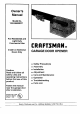
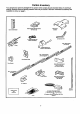
Owner's Manual Model No. 139.53669SRT For Residential and Light Duty Commercial Use Install on Sectional Doors Only CRRFTSMRN® GARAGE DOOR OPENER • Safety Precautions Caution: Read and follow all safety rules and operating instructions before first use of this product. • Assembly • Installation • Adjustment • Care and Maintenance • Operation • Troubleshooting • Parts List Fasten the manual near the garage door after installation.
Contents . Page A review of safety alert symbols ............................. 2 You'll need tools ..................................................... 3 Safety information ................................................... 3 Testing your garage door for sticking, binding and balance .......................................................... 3 Illustration of sectional door installation ................. 4 Carton inventory ..................................................... 5 Hardware inventory ....
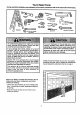
You'll Need Tools During assembly, installation and adjustment of the opener, instructions will call for hand tools shown below. Level Tape Measure _ Hack Saw Wire Cutters Claw Hammer 3/16", 5/16" and 5/32" Oda Bits Pliers Sts_adder Sctewddvet Adjus_bfe End Wrench An unbalanced garage door might not reverse when required and someone under the door could be seriously injured or killed. If your garage door binds, sticks or is out of balance, call for professional garage door service.
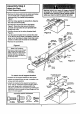
Before you begin, survey:your garage area. Do any of the following COnditionsapply to you? Before you begin, survey your garage area to see whether any of the conditions below apply to your installation. HorizoNtaland vertic_ reinfofr.,ernent is needed fo_ligh_veightgarage doors (flberg_tss.steel aluminum,door wireglasspanels, etc,). See page22 fordetails. FINISHED CSIUNG Supportbracket& fasteninghardware Lsrequired. See page 15. SI_ in chain tension is nermal when garage door is dosed.
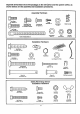
Carton Inventory Your garage door opener is packaged in two cartons which contain all parts illustrated below. If anything is missing, carefully check the pecking material. Parts may be "stuck" in the foam. Hardware for assembly and installation is shown on page 6. Tilme-Functk_ Remote Control withV'_O_Clip Door ControlButton Rail Support Br_c_,et Curved DoorAnn Rail o Back Section (To Opener) Ttotiey Rail - Center Section (Interci_angeable.
Separate all hardware from the packages in the rail carton and the opener carton, as shown below, for the assembly and installation procedures. Assembly Hardware i Hex Screw 1/4".20xS/r (2) #8-32x_8" _lll@illIPIlll0 Washemd Screw 5/16".
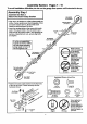
Assembly Section: Pages 7- 10 To avoid installation difficulties, do not run the garage door opener until instructed to do so. Assembly Step I Assemble the Rail & Attach the Chain Pulley Bracket RAIL BACK (TO OPENER) • Align the 4 rail sections on a fiat surface exactly as shown. Center sections are interchangeable. Front and back sections are not. Be sure the arrow labels are pointing toward the door.
Hardware Shown Actual Size Assembly Step 2 Install the Trolley on the Rail • Attach the threaded shaft to the trolley with the lock washer and nuts as shown. NUt 5/16" LOCkWasher S/t6"-18 Outer Nut 5/16"_ • As a temporary stop, insert a screwdriver into the hole in the front end of the rail. • Slide the trolley assembly along the rail to the screwdriver stop. If trolley hits against any nuts on the rail, the bolts and nuts were attached from the wrong side and must be repositioned. Review Step 1.
Assembly Step 4 Attach the Chain & Rail Support Bracket • Remove the chain end from the carton and fasten it to the trolley with a master link from the hardware bag. See master link procedure, Figure 1. Chain_,%orodmt • With the trolley against the screwdriver, dispense the chain around the pulley. • Proceed back around the rail to the opener, Figure 2. Guide the chain around the chain spreader and sprocket. Be sure sprocket teeth engage the chain.
Assembly Step 5 Tighten the Chain • Spin the inner nut and lock washer down the threaded shaft, away from the trolley. Lock Outer Nut • To tighten the chain, turn outer nut in the direction shown. As you turn the nut, keep the chain from twisting. Wastler To TightenOuterNut --_--_ --_ _,_ "Nu' v • When the chain is approximately 1/2" above the base of the rail at its midpoint, re-tighten the inner nut to secure the adjustment.
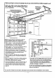
Installation Section: Pages 11 - 23 I Installation Step 1 Determine Header Bracket Location __ VG_Cal Guideline 2=(4 Finished Ceiling If the header bracket is not rigidly fastened to a structural support on the header wall or ceiling, the safety reverse system may not work properly (see page 26). The door might not reverse when required, and could cause serious injury or death. The garage door springs, cables, pulleys, brackets and their hardware are under extreme tension.
the HeaderStep Bracket Installation 2 You can attach the header bracket either to the wall above the garage door, or to the ceiling. Follow the instructions which will work beet for your particular requirements. I Install Fasten the Header Bracket to the Wall • Center the bracket on the vertical guideline with the bottom edge of the bracket on the horizontal line as shown (with the arrow pointing toward the ceiling). • Ma_ either set of bracket holes (do not use the holes designated for ceiling mount).
Attach the Rail to the Header Bracket Installation Step 3 I • Position the opener on the garage floor below the header bracket. Use packing material as a protective base. If the door spring Is In the way you'll need help. Have someone hold the opener securely on a temporary support to allow the rail to clear the spring. • Position the chain pulley bracket against the header bracket. • Align the bracket holes and join with a clevis pin as shown. • Insert a ring fastener to secure.
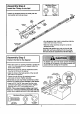
I Installation Step 4 Position the Opener A 2x4 laid fiat is convenient for setting an ideal door-to-rail distance. You will need help at this point if the ladder is not tall enough. • Raise the opener onto a stepladder. • Open the door all the way and place a 2x4 laid fiat on the top section beneath the rail. Rail 2x4 • ff the top panel hits the trolley when you raise the door, pull down on the trolley release arm to disconnect the inner and outer sections.
Installation Step 5 Hang the Opener Two representative installations are shown. Yours may be different. Hanging brackets should be angled, Figure -1, to provide rigid support. On finished ceilings, Figure 2, attach a sturdy metal bracket to structural supports in ceiling before installing the opener. The bracket and fastening hardware are not provided. See accessory page 34. Figure I • Measure the distance from each side of the opener to the structural support.
I Installation Step 6 Install the Door Control Children operating or playing with a garage door opener can injure themselves or others. The garage door could close and cause serious injury or death. Install the Door Contro! (or any additional pdsh buttons) out of the reach of children and av/ay from all moving parts of the door and door hardware, but where the garage door Is visible. Do not allow children to operate the ptmh button or the remote controls.
I Installation Step 7 Install the Light • Install a 75 watt maximum light bulb in the socket. The light will rum ON and remain lit for approximately 4-1/2 minutes when power is connected. Then the light will rum OFF. Light Bulb 75 Walt Max._ • If the bulb bums out prematurely due to vibration, replace with a standard neck "Garage Door Opener = bulb.
Installation Electrical Step 9 Requirements I 1:o reduce the risk of electric shock, your garage door opener has a grounding type plug with a third grounding pin. This plug will onlyflt into a grounding type outlet. If the plug doesn't fit into the outlet you have, contact a qualified electrician to install the proper outlet. Right do run installation the opener difficulties, at this time.
Safety Reversing System Information you'll need before you begin the installation of the safety reversing sensor. The safety reversing sensor must be connected and aligned correctly before the garage door opener will move in the down direction. This is a required safety device and cannot be disabled. Without a properly working safety reversing sensor, persons (particularly children) could be killed by a closing garage door. Read and follow all instructions.
Installation Step 10 Install the Safety Reversing I I Sensor Figures 2 and 3 show assembly of brackets and "C" wrap based on the recommended installation of the sensors as shown on page 19, Figure 2 MounUng enc_th . However, Figures 4 and 5 are variations which may fit your installation requirements better. Make sure the wraps and brackets are allgned so the sensors will face each other across the garage door.
Figure 6 • Center each sensor unit in a "C" wrap with lenses pointing toward each other across the door (see Figure 6). Indicator Ugm Secure sensors with the hardware shown. Finger tighten the wing nut on the receiving eye to allow for final adjustment. Securely tighten the sending eye wing nut. 114-20 x 1-1/2" Hex Bolt , Run the wires from both sensors to the opener. Use insulated staples to secure wire to wall and ceiling. Trouble Shooting 1.
Installation Step 11 I I Fasten Door Bracket A horizontal brace should be long enough to be secured to 2 vertical supports. A vertical brace should cover the height of the top panel. The illustration shows one piece of angle iron as the horizontal brace. For the vertical brace, 2 pieces of angle iron are used to create a "U"-shaped support.
I Installation Step 12 Connect Door Arm to Trolley Make sure garage door is fully closed. Pull the emergency release handle to disconnect the outer fr611ey from the inner trolley. Slide the outer trolley back (away from the door) about 2" as shown In Figures 1, 2 and 3.
Adjustment Section: Pages 24 - 26 Adjustment Step 1 Adjust the UP and DOWN Limits Do not make any limit adjustments until the safety reversing sensors are completely installed. Limit adjustment settings regulate the points at which the door will stop when moving up or down. The door will stop in the updirsction if anything interferes with door travel.
Adjust the Force Step Adjustment 2 I Force adjustment controls are located on the back panel of the opener. Force adjustment settings regulate the amount of power required to open and close the door. The door will stop in the up direction if anything interferes with its travel. The door will reverse in the clowndirection if anything interferes with its travel (including binding or unbalanced doors). Too much force on the door will interfere with the proper operation of the safety reverse system.
Adjustment Step 3 Test The Safety Reversing Sensor I • Press the Door Control button to open the door. • Place the opener carton in the path of the door. • Press the Door Control button to close the door. The door will not move more than an inch, and the opener light will flash. Professional service is required ff the opener closes the door when the safety reversing sensor is obstructed.
IMPORTANT SAFETY INSTRUCTIONS To reduce the risk of severe injury or death to persons: 1. READ AND FOLLOW ALL INSTRUCTIONS. 2. Do not permit children either to operate or to play with the opener. Keep a remote control in a location inaccessible to children. 3. Operate opener only when the door is in full view and free from any obstruction. Keep the door In sight until it is completely closed. NO ONE SHOULD CROSS THE PATH OF THE MOVING DOOR. 4. Check safety reversal system monthly. See page 26.
Operation of Your Opener Activate the opener with any of the following: • The Remote Control: Hold push button down until the door starts to move. • The Door Control. Hold push button down until the door starts to move. • The Outdoor Key Switch or Keyless Entry. (See Accessories.) When the opener is activated with the Safety Reversing Sensor installed and correctly aligned: t. If open, the door will close. If closed, it will open. 2. If closing, the door will reverse. 3.
Receiver and Remote Control Programming NOTICE: To complywith FCC ruleS,ad_ustmantor modirK:alfon Ofthis receiverand/or transmitter are prohibited,exseplfor changingthe code settingor reglacingthe batten/.THERE ARE NO OTHER USER SERVICEABLE PARTS. Children operating or playing with a garage door opener can Injure themselves or others. The garage door could close and cause serious Injury or death. Do not allow children to operate the door control or remote controls.
Having a Problem? Situation Probable The opener doesn't operate from either the door control or the remote control: 1. Does the opener have electric power'?. Plug a lamp intothe outlet. If it doesn't light, check the fuse box or the circuit breaker. (Some outletsare controlledby a wall switch.) Cause & Solution 2. Have you disabled all door locks? Review installationinstructionwarnings on Page 10. 3. Is there a build-up of ice or snow under the door?.The door may be frozen to the ground.
Having a Problem? (continued) Situation The door opens but won't close: Probable Cause & Solution 1. If the opener light blinks, check the safety reversing sensor. See page 21. 2. If the opener light does not blink and it is a new installation, check the down force. See Adjustment Step 2, page 25. For an existing installation, see below. Repeat the safety reverse test after the adjustment is complete• The door reverses for no apparent reason and opener light doesn? blink: 1.
Repair Parts Rail Assembly Parts 5 IKEY !NO. i I 2 3 4 5 6 4 7 8 9 Installation PART NO. 41A4166-1 41 A4873 3 4 5 6 7 8 9 10 11 12 13 14 15 1A995 41A2780 4tA3489 1B4935 1B4934 1B4933 83A4 41A4554 41A4937 DESCRIPTION Master linkkit Chain pulleybracket Complete trolleyassembly Rail assy,to door end Rail assy center secUons(2) Rail assy. to powerhead Rail grease Chain Rail asey hardwarekit (Includes hardwarelistedon page 5), Parts -1 KEY NO. PART NO.
Repair Parts Opener Assembly Parts r--p_u"_.._==" ,I, 17 =rL._-.-_ ]_ 15 Wire co_,== KEY NO. PART NO. 1 41C5069 =2 144B18 i 3 41C4470 41A2817 5 6 7 8 9 1430100 175B88M 30B432 12A461 41A3150 14 , I g _'_ - LJ L-8 - I L. , 12 ! co°_== Wi,o 11 DESCRIPTION Rail support bracket assembly kit Pulley (Chain) Gear and sprocket assy.
Accessories Sears offers many useful accessories fro your garage door opener. They are illustrated below with Sears modal numbers and descdptions. 139.53702 Emergency Key Release: 139.53879 Required for a garage with NO access door. Enables homeowner to open garage door manually from outside by disengaging trolley. 139.53703 Outdoor Key Switch: includes visor clip. 139.03859 Operates the garage door automatically from outside when remote control is not handy.
Index Access Door/Emergency Key Release Accessory ....................................................................................... Chain Tension ............................................................................................................................................ 4, 34 4, 10, 31 Electrical Safety Warnings ..................................................................................................................
For professional Installatlon Call 24 hours a day, 7 days a week 1-800-865-6500 For the repair or replacement parts you need Call 7 am - 7 pm, 7 days a week 1-8OO-366-PART (1-800-366-7278) For in-home major brand repair service Call 24 hours a day, 7 days a week 1-800-4-REPAIR (1-800-473-7247) For the location of a Sears Repair Service Center in your area : Call 24 hours a day, 7 days a week 1-800-488-1222 For information on purchasing a Sears Maintenance Agreement or to inquire about an existing Agr