Owner's Manual Model No. 139.53661SRT3 139.53671SRT3 139.53672SRT3 139.53673SRT3 139.53674SRT2 139.53677SRT3 For Residential Use Only CRRFTSMRN® GARAGE DOOR OPENER Caution: Read and follow all safety rules and operating instructions before first use of this product, Fasten the manual near the garage door after installation.
Contents Page A review of safety alert symbols ................................. 2 You'll need tools.......................................................... 3 Safety information regarding garage door looks and ropes .................................................................. 3 Testing your garage door for sticking, binding and balance ............................................................... 3 Illustrationof sectional door installation .....................
You'll Need Tools During assembly, installation and adjustment of the opener, instructionswill call for hand tools shown below. Pencil OOQOIQQO o Hack .% Saw Tape Measure Wire Cutters 3/16', 5/16 and Claw Hammer 5/32" Drill Bits Screwdriver Stepladder Adjustable End Wrench To avoid damage to the garage door and opener, disable locks before installing and operating the opener. Use a wood screw or nail to hold locks in the "open" (unlocked) position.
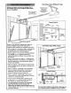
Before you begin, survey your garage area to see whether any of the conditions below apply to your installation. Herizontal FINISHED CEILING Supporl bracket & fastening hardware is required. See page 17. and vertical reinforcement is needed for lightweight garage doors (fiberglass, steel, aluminum, door with glass panels, etc.). See page 24 for details.
J__ --_ V_ One-Piece Before you begin, survey your garage area to see whether any of the conditions below apply to your installation. Door Without FINlu_Ct_HEDbCr_Fd^L_N,G &fastening Track _ _ _ hardware is required. S_n o h;intet_nSiOn See psge 17. garage door is closed. Hewd/r )l[F/_ _ I Nt 0 _ Door Bracket _v J J II r_ader ,.,_J]iI ._-_ ..... Gap between floor and bottom of door must not exceed 1/4". rs=ng Sensor Hope & Nandle Door _\Xl Safety Reversing Sensor Based o
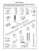
Carton Inventory Your garage door opener is packaged in two cartons which contain parts illustrated below. Accessories will depend on model purchased. If anything is missing, carefully check the packing material. Parts may be "stuck" in the foam. Hardware for assembly and installation is shown on page 7.
Separate all hardware from the packages in the rail carton and the opener carton, shown below, for the assembly and installation procedures.
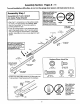
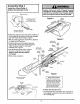
Assembly Section: Pages 8 - 11 To avoid installation difficulties, do not run the garage door opener until instructed to do so. Make sure bolt necks are seated tn the square ,_= holes and rails are aligned before you tighten lock nuts.(See right and wrong views). Improper assembly can cause jerky trolley operation,noise and/or Right nuisance door reversals. Assembly Step 1 Assemble the T-rail & Attach the Cable Pulley Bracket • Align the 3 T-rail sections on a flat surface exactly as shown.
Assembly Hardware Shown Actual Size Step 2 Install the Trolley on the T-rail ©© • Attach the threaded shaft to the trolley with the lock washer and nuts as shown. Lock Washer 5/16" Trolley Nut 5/16" - 18 Lock Washer 5/16' Outer Nut Inner Nut 5/16" Trolley Threaded Shaft Trolley Temporary Stop Screwdriver • As a temporary stop, insert a screwdriver hole in the front end of the T-rail. into the • Slide the trolley assembly along the rail to the screwdriver stop.
Assembly Step 4 Install the Chain/Cable & Attach the Sprocket Cover Dispensing Cadon Figure 2 Leave Chain and Cable Opener Sprocket Inside Dispensing Carton to Prevent Kinking. Keep Chain and Cable Taut When DLspensing • Detach the cable loop from the carton and fasten it to the trolley with a master link from the hardware bag. See master link procedure, Figure 1. Figure 3 I • With the trolley against the screwdriver, dispense the cable around the pulley.
Assembly I Step 5 Tighten the Chain & Cable Lock Washer Outer Nut • Spin the inner nut and lock washer down the threaded shaft, away from the trolley. To Tighten Outer Nut _,._-'_ To tighten the chain, turn outer nut in the direction shown. As you turn the nut, keep the chain from twisting. I_ When the chain is approximately 1/2" above the base of the T-rail at its midpoint, re-tighten the inner nut to secure the adjustment.
Installation Installation Determine Section: Pages 12 - 27 Step 1 Header Bracket Location If the header bracket is not rigidly fastened to a structural support on the header wall or ceiling, the safety reverse system may not work properly (see page 30), The door might not reverse when required, and could cause serious injury or death. Installation procedures vary according to garage door types. Follow the instructions which apply to your door.
Read the Safety instructions on page 12. They also apply to doors without tracks. Infinished Header Wall Vertical Centerline 2x4 • Close the door and mark the inside vertical centerline of your garage door. Extend the line onto the header wall above door. If headroom clearance is minimal, you can install the header bracket on the ceiling. See page 14.
Installation Install You can attach the header bracket either to the wall above the garage door, or to the ceiling. Follow the instructions which will work best for your particular requirements, Step 2 the Header Bracket Fasten the Header Bracket to the Wall • Mark either set of bracket holes (do not use the holes designated for ceiling mount). Drill 3/16" pilot holes and fasten the bracket securely to a structural support with the hardware provided.
Attach the T-rail Step to the 3Header Installation Bracket [ • Position the opener on the garage floor below the header bracket. Use packing material as a protective base. If the door spring is in the way you'll need help. Have someone hold the opener securely on a temporary support to allow the T-rail to clear the spring, Header Sracket Cable • Position the cable pulley bracket against the header bracket, Bracket • Align the bracket holes and join with a clevis pin as shown.
Installation Position Step 4 the Opener Follow instructions type as illustrated. which apply to your door A 2x4 laid flat is convenient for setting an ideal door-to-T-rail distance. T rail • Raise the opener onto a stepladder. 2x4 You will need help at this point if the ladder is not tall enough.
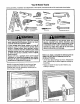
Installation Step 5 Hang the Opener Two representative installations are shown. Yours may be different. Hanging brackets should be angled, Figure 1, to provide rigid support. On finished ceilings, Figure 2, attach a sturdy metal bracket to structural supports before instattingthe opener. The bracket and fastening hardware are not _rovided. See accessory page 38. Figure I Supports • Measure the distance from each side of the opener to the structural support.
Installation Install the Door Step Control 6 I Do not connect to live electrical w/ring. Connect only to 24 Volt low voltage wires. Connection to live wires or higher voltage may cause serious injury from shock, burn or electrocution. Children operating or playing with a garage door opener can injure themselves or others. The garage door could close and cause serious injury or death.
6.AttachtheUserSafetyInstruction labeltothewall nearthedoorcontrol,andthe Maintenance Instructionlabelin a prominentlocationonthe insideofthegaragedoor. Do NOT connect the power and operate the opener at this time. The trolley will travel to the full open position but will not return to the close position until the sensor beam is connected and properly aligned. See Safety Reversing Sensor instructions beginning on page 21. Page 32 explains how to use the door control.
Installation Electrical Step 9 Requirements To prevent electrocution or fire, installation and wiring must be in compliance with local electrical and building codes. To reduce the risk of electric shock, your garage door opener has a grounding type plug with a third grounding pin. This plug will onlyfit into a grounding type outlet. Do NOTuse an extension cord, 2-wire adapter, or change the plug in any way to make it fit i your outlet.
Safety Reversing System Information you'll need before you begin the installation and aligned correctly before the garage door The safety sensor connected opener will reversing move in the down mustbe direction. This is a required safety device and cannot be disabled. Installation procedures and one-piece doors. of the safety reversing sensor, Without a properly working safety reversing sensor, persons (particularly children) could be injured or killed by a closing garage door.
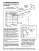
Installation Step 10 I Install the Safety Reversing I Sensor Figure 2 Figures 2 and 3 show assembly of brackets and "C" wrap based on the recommended installation of the sensors as shown on page 21. Mounting Bracket With Square Holes However, Figures 4 and 5 are variations which may fit your installation requirements better. Make sure the wraps and brackets are aligned so the sensors will face each other across the garage door.
• Centereachsensorunitin a "C"wrapwithlenses pointingtowardeachotheracrossthedoor(see Figure6). Securesensorswiththehardwareshown.Finger tightenthewingnutonthereceiving eye to allow Figure 6 Indicator Light for final adjustment. Securely tighten the sending eye wing nut. 1/4-20 x 1-1/2" Hex Soft Run the wires from both sensors to the opener. Use insulated staples to secure wire to wall and ceiling. Trouble • Strip 1/4" of insulation from each set of wires.
Installation Step 11 Fasten Door Bracket Follow instructions which apply to your door type as illustrated below or on page 25. A horizontal brace should be long enough to be secured to 2 vertical supports. A vertical brace should cover the height of the top panel. The illustration shows one piece of angle iron as the horizontal brace. For the vertical brace, 2 pieces of angle iron are used to create a "U"-shaped support.
Please read and comply with the warnings They apply to one-piece doors also. Header Wall -- Finished and reinforcement instructions on page 24. Ceiling -- 2x4 Support Header Bracket Bracket Horizontal and vertical reinforcement is needed for Placement of Door Bracket lightweight garage doors (fiberglass, aluminum, steel, door with glass panel, etc.).
Installation Connect Step 12 Door Arm to Trolley Follow instructions which apply to your door type as illustrated below and on page 27. Make sure garage door is fully closed. Pull the emergency release handle to disconnect the outer trolley from the inner trolley. Slide the outer trolley back (away from the door) about 2" as shown in Figures 1, 2 and 3. Figure 1 : Figure 2: • Fasten straight door arm section to outer trolley with the 5/16"xl" clevis pin. Secure the connection with a ring fastener.
Assemble the Door Arm: • Fasten the straight and curved door arm sections together to the longest possible length (with a 2 or 3 hole overlap). Door Ring Washers _5/16e"rs _Lock 5/16" Brack_ • With the door closed, connect the straight door arm section to the door bracket with the 5/16"xl-1/4" clevis pin. C{evis Pin Straight _----_'_" Screws • Secure with a ring fastener. 5/16"-1g Nuts } I / \/I _"" 6116"-1 8x7/8 ,F_ rved Door Arm On one-piece doors, before connecting the door arm to the trol
Adjustment Section: Pages 28 - 30 Adjustment Adjust Step 1 the UP and DOWN Limits Do not make any limit adjustments until the safety reversing sensors are completely installed. Limit adjustment settings regulate the points at which the door will stopwhen moving up or down. The door will stop in the up direction if anything interferes with door travel. The door will reverse in the down direction if anything interferes with the door travel (including binding or unbalanced doors).
Adjustment I Step 2 Adjust the Force Force adjustment controls are located on the back _anel of the opener. Force adjustment settings regulate the amount of power required to open and close the door. The door will stop in the up direction if anything interferes with its travel. The door will reversein the down direction if anything interferes with its travel (including binding or unbalanced doors).
Adjustment Step 3 Test The Safety Reversing Sensor I • Press the remote control push button to open the door. • Place the opener carton in the path of the door. • Press the remote control push button to close the door. The door will not move more than an inch, and the opener light will flash. Professional service is required if the opener closes the door when the safety reversing sensor is obstructed.
IMPORTANT SAFETY INSTRUCTIONS To reduce the risk of severe injury or death to persons: 1. READ AND FOLLOW ALL INSTRUCTIONS. 2. Do not permit children either to operate or to play with the opener. Keep remote control in a location inaccessible to children. 3. Operate opener only when the door is in full view and free from any obstruction. Keep the door in sight until it is completely closed. NO ONE SHOULD CROSS THE PATH OF THE MOVING DOOR. 4. Check safety reversal system monthly. See page 30.
Operation of Your Opener Activate the opener with any of the following: • The Remote Control: Hold push button down until the door starts to move. • The Door Control: Hold push button down until the door starts to move. Weak or broken springs could allow an open door to fall (either rapidly or unexpectedly), resulting in serious injury, death or property damage. If possible, use the emergency release rope and handle onlywhen the door is fully closed. • The Outdoor Key Switch or Keyless Entry.
Receiver and Remote Control Programming SI ,CIJRI'I -"I; To comply with FCC rules, adjustment or modifications of this receiver and/or transmitter are prohibited, except for changing the code setting or replacing the batte W. THERE ARE NO OTHER USER SERVICEABLE PARTS, Your garage door opener receiver and remote control have been pre-set at the factory. The door will open when you press the LARGE remote control push button.
Having a Problem? Situation Probable Cause and Solution The opener doesn? operate from either the Door Control or the remote control: 1. Does the opener have electric power? Plug a lamp into the outlet. If it doesn't light, check the fuse box or the circuit breaker. (Some outlets are controlled by a wall switch.) 2. Have you disabled all door locks? Review installation instruction warnings on Page 11. 3. Is there a build-up of ice or snow under the door? The door may be frozen to the ground.
Having a Problem? (continued) Situation Probable Cause & Solution The door opens but won't close: 1. If the opener lights blink, check the safety reversing sensor. See page 23. 2. If the opener lights do not blink and it is a new installation, check the down force. See Adjustment Step 2, page 29. For an existing installation, see below. Repeat the safety reverse test after the adjustment is complete. The door reverses for no apparent reason and opener lights don't blink: 1.
Repair Parts, rail assembly and installation Refer to Parts Diagram document for part info.
Repair Parts, opener assembly Refer to Parts Diagram document for part info.
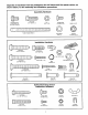
Accessories Sears offers many useful accessories for your garage door opener. They are illustrated below with Sears model numbers and descriptions. 139.53702 ,f 139.53681 Emergency Key Release: Requiredfor a garage with NO access door. Enables homeowner to open garage door manually from outside by disengaging trolley. Outdoor Key Switch: Operates the garage door automatically from outside when remote control is not handy. 10 Foot Rail Extension: 139.
Index Access DoorlOutside Key Release Accessory ............................................................................................... 4, 5 Chain Tension .............................................................................................................................................. 4, 5, 11 Electrical Safety Warnings ........................................................................................................................
For professional installation Call 24 hours a day, 7 days a week 1-800-865-8500 For the repair or replacement parts you need Call 7 am - 7 pro, 7 days a week 1-800-366-PART (1-800-366-7278) For in-home major brand repair service Call 24 hours a day, 7 days a week 1-800-4-REPAIR (1-800-473-7247) For the location of a Sears Repair Service Center in your area Call 24 hours a day, 7 days a week 1-800-488-1222 For information on purchasing a Sears Maintenance Agreement or to inquire about an existing Agreeme