
Manual

CRAFTSMAN®
OWNER'S INSTRUCTIONS
Close door and disconnect power to the garage door
opener before proceeding.
Model 139.53725
Ten-Foot Rail Extension Kit
The trolley must be In down (#loBed door) posit/on during
asammb/y and Insta//at/on. If you have e completelyinstalled
garage door opener, the rail/openerassembly must be taken
down. UP and DOWN Limitsmustbe readjustedafter
installation.
Opener hanging bracketswillrequirereposltloningdue to
increased raillength.
ffthle lea new Itmle/k_on, replacethe front(header) railin
your opener cartonwith thelonger one in this kit.Add the
center railin this kit as the second orthird rail, creating• four
railassembly.Use the chain/cable assembly and longer
emergencyrelease rope in this kit in piece ofthose packaged
with youropener. Complete the assembly,installation,and
adjustment ofyour opener accordingto yourOwner's Manual.
/f thle le an exletfng//role/let/on, oon#nue an fo//ow_.
1. Pull clownon the emergency release handle,then
disconnectthe trolleyfrom the doorarm.
2. Disconnectthe rail/opener assemblyfrom the header
bracket and hanging brackets,and place iton the floor.
3. Remove the sprocketcover from the powerhead and sat
aside.
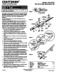
4. Remove theouter nut (Figure 1) from the trolleyshaftand
set aside.
5. Disconnectthe two master linkeseemblias from the trolley
(Figure 2) and discard.
6. Remove Idler pulleyassembly and set aside.
7. Remove the chein/ceble assembly and discard.
8. Remove the 1/4"-20xl-3/4 boltand lock nutfrom thetrolley
stop holein the frontrailand set aside.
9. Push the trolleyback toward the opener head. Disconnect
the frontrailsectionby using• screwdrivertip to pry up the
outer tab on each side ofthe rail (Figure3), then slide itoff
the center rail. Discard the front rail.
10. Alignthe new front and center railswith the existingrail
assemuy,ksepingtheemaUho_sa_g thesameedge,and
the cutout"windov/'et the front (heeder) end.Be scre to
keep railsrightside up: theidler pulley boltholeabove the
window@ larger on top ofthe rai/then on the bottom.81ide
the new centerrailontothe assembly, then add the front rail.
Tabsetongthes_e w_lockthtoplace.
11. Asa temporary trolleystop,clamp a locking pliers ontothe
rail, 8" fromthe center of the idler pulleyhole, as shown in
Figure4. Slidethe trolleyassembly to thispoint.
12. Refer to yourowner's manual to completetheassembly, re-
installationand adjustment of your opener
13. Replace the old emergency release rope withthe new,
longerreplacement rope.
14. Reconnect powerand operate thedoor in the UP direction.
15. Increase the UP travel limitby turningthe UP limit
adjustment screwin a dockwlee directionas shown on
label. One turnequals 2" of travel,
Ma_ Ur_ 0u_ i1_: _roll_SP_t
Figure
[_ Lo_kWamw
F/gure 2
Loop
1/4"-20x1_4
Troile
Hole
Mender
LinkBar
Figure 4
ld_r
Cut-Out
Stop
I_w'tNo.
183C158-11
183C157-8
IA5249-2
26,A53
1,4995
Oe_rlptlon
Header rail extension
C.enterrailsection
IO"Chal'n,CableAssembly
Rope
Master Unk tot
at),
I
I
I
I
1
o1_o, Sear_ Roobu_& 0o,
114A2408 NI Flleh_Rue_vod PdntedinMoxioo