Owner's Manual 1/2 HP GARAGE DOOR OPENER For Residential Use Only Model No: 139.53978SRT CAUTION: Read and follow all safety rules and operating instructions before first use of this product. [] Safety Precautions [] Assembly [] Installation [] Adjustment [] Maintenance Fasten the manual near the garage door after installation. [] Operation [] Troubleshooting [] Parts List Complies with UL 325 ,/"_'_ regulations effective _ U| | January 1, 1993 Sears, Roebuck and Co.
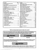
Contents Page A review of safety alert symbols ................................. 2 You'll need tools.......................................................... 3 Contents Page Install the light and lens ................................................. 19 Attach emergency release rope and handle ................. 19 Safety information regarding garage door locks and ropes .................................................................. 3 Electrical requiramemts ........................................
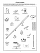
You'll Need Tools During assembly, installation and adjustment of the opener, instructions will call for hand tools shown below. Stepladder _ckets _ An unbalanced garage door might not reverse when required and someone under the door could be seriously injured or killed. If your garage door binds, sticks or is out of balance, call for professional garage door service. Garage doors, door springs, cables, pulleys, brackets and their hardware are under extreme tension and can cause serious Injury or death.
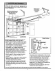
Before you begin, survey your garage area to see whether any of the conditions below apply to your installation. FINISHED CEILING Support bracket & fastening hardware is required. See page 17. Horizontal and vertical reinforcement is needed for lightweight garage doors (fiberglass, steel, aluminum, door with glass panels, etc.).
One-Piece Before you begin, survey your garage area to see whether any of the conditions to your installation. Door without Track FINISHED CEILING below apply support bracket "_ &fastening _'_ _ h_rdware is required. See page 17. Header Wall _ _ _Trolley Stop Bolt Cable Trolley EmergenCy Release Rope & Handle leader Reversinc ap between floor and bottom Safety of door must not exceed 1/4".
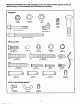
Carton Inventory Your garage door opener is packaged in two cartons which contain parts illustrated below. Accessories will depend on model purchased, if anything is missing, carefully check the packing material. Parts may be "stuck" in the foam. Hardware for assembly and installation is shown on page 7.
Separate all hardware from the packages in the rail carton and the opener carton, as shown below, for the assembly and installation procedures.
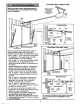
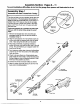
Assembly Section: Pages 8 - 11 To avoid installation difficulties, do not run the garage door opener until instructed to do so. Assembly Step I Assemble the Rail & Install I the I Trolley The front rail has a cut out "window"at the door end (see illustration). The hole above this window is larger on the top of the rail than on the bottom. A smaller hole 3-1/2" away is close to the rail edge. The back rail has a similar hole close to the edge, about 4-3/4" from the far end.
Assembly Step 2 I I Fasten the Rail to the Opener • Insert a 1/4"-20xl -3/4 bolt into the cover protection bolt hole on the back end of the rail as shown. Tighten securely with a 1/4"-20 lock nut. To fasten rail, use only those screws mounted in the top of the opener. Any other screws will cause serious damage to the opener. • Remove the two screws from the top of the opener. • Place the U bracket, flat side down, on the opener and align the bracket holes with the screw holes.
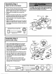
Assembly Step 4 Install the Chain/Cable and Attach the Sprocket Cover 1. Pull the cable around the idler pulley and toward the trolley. 2. Connect the cable loop to the retaining slot on the trolley, as shown: • From below, push pins of master link bar up through cable loop and trolley slot. Dispensing Carton • Push master link cap over pins and past pin notches. Leave Chainand Cable Inside D_spensing Carton to PreventKinking.
Assembly Step 5 Tighten the Chain I • Spin the inner nut and lock washer down the threaded shaft, away from the trolley. Figure I o=_ Lo_ Tro,.y Nut Washer • To tighten the chain, turn outer nut in the direction shown (Figure 1). ToT_.,_n Outer Nut.--_ I ! Shaft / • When the chain is approximately 1/2" above the base of the rail at its midpoint, re-tighten the inner nut to secure the adjustment. Sprocket noise can result if chain is too loose.
Installation Section: Pages 12 - 27 Installation Step I Determine Header Bracket Location If the header bracket Is not rigidly fastened to a structural support on the header wall or ceiling, the safety reverse system may not work properly (see page 30). The door might not reverse when required, and could cause serious injury or death. Installation procedures vary according to garage door types. Follow the instructions which apply to your door.
Read the Safety instructions on page 12. They also apply to doors without tracks. Header Wall Vertical Centerflne 2x4 • Close the door and mark the inside vertical centerline of your garage door. Extend the line onto the header wall above door. If headroom clearance is minimal, you can install the header bracket on the ceiling. See page 14.
Install the Header Bracket Installation Step 2 You can attach the header bracket either to the wall above the garage door, or to the ceiling. Follow the instructions which will work best for your particular requirements. I Wall Header Bracket Installation • Mark the vertical set of bracket holes. Drill 3/16" pilot holes and fasten the bracket securely to a structural support with the hardware provided.
Attach the Rail to the Header Installation Step 3 Bracket I NOTE: (Optional) With an existing Craftsman installation, you may re-use the old header bracket with the two plastic spacers included in the hardware bag. Place the spacers inside the bracket on each side of the rail, as illustrated. • Position the opener on the garage floor below the header bracket. Use packing material as a protective base. If the door spring is in the way you'll need help.
Installation Step 4 Position the Opener Follow instructions type as illustrated. which apply to your door A 2x4 laid flat is convenient for setting an ideal door-to-T-rail distance. Outer Trolley Inner Trolley • Raise the opener onto a stepladder as shown, You will need help at this point if the ladder is not tall enough. • Open the door all the way and place a 2x4 laid flat on the top section beneath the rail.
I Installation Step 5 Hang the Opener Two representative installations are shown. Yours may be different. Hanging brackets should be angled, Figure 1, to provide rigid suppod. On finished ceilings, Figure 2, attach a sturdy metal bracket to structural supports before installing the opener. The bracket and fastening hardware are not provided. See accessory page 38. 1. Measure the distance from each side of the opener to the structural support. Figure I Supports 2.
I Installation Step 6 Install the Door Control Locate the door control within sight of the door at a minimum height of 5 feet where small children cannot reach, and away from all moving parts of the door and door hardware. The door control is typically attached directly to the wall. If installing into drywall, drill 5/32" holes and use the anchors provided. For pre-wired installations (as in new home construction), Console models may be mounted to a standard single gang box (Figure 2). 1.
6. Attach the User Safety Instruction label to the wall near the door control, and the Maintenance Instruction label in a prominent location on the inside of the garage door. Do NOT connect the power and operate the openerat this time. The trolley will travel to the full open position but will not return to the close position until the sensor beam is connected and properly aligned. Page 32 explains how to use the door control. See Safety Reversing beginning on page 21.
Installation Electrical Step 9 Requirements I I To prevent electrocution or fire, installation and wiring must be in compliance with local electrical and building codes. To reduce the risk of electric shook, your garage door opener has a grounding type plug with a third grounding pin. This plug will onlyfit into a grounding type outlet. Do NOTuse an extension cord, 2-wire adapter, or change the plug in any way to make it fit your outlet.
The Safety Reversing System IMPORTANT INFORMATION ABOUT THE SAFETY REVERSING SENSOR The safety reversing sensor must be connected and aligned correctly before the garage door opener will move in the down direction. This is a required safety device and cannot be disabled. Without a properly working safety reversing sensor, persons (particularly children) could be injured or killed by a closing garage door.
Figure 2 the Safety Step Reversing Installation 10 Install Sensor DOOR TRACK MOUNT (Right Side) I • INSTALLING THE BRACKETS Track ',Door Up Indicator light Be sure power to the opener is disconnected. Install and align the brackets so the sensors will face each other across the garage door, with the beam from 4 - 6" above the floor. Bracket They may be installed in one of three ways, as follows.
MOUNTING AND WIRING THE SAFETY SENSORS Figure 5 • Slide a 1/4"-20xl/2" carriage bolt head into the slot on each sensor. Use wing nuts to fasten sensors to brackets, wRh lenses pointingtoward each other across the door. Be sure the lens is not obstructed by a bracket extension. See Figure 5. Wing nut 1/4" 20x1/2" • Finger tighten the wing nuts. • Run the wires from both sensors to the opener. Use insulated staples to secure wire to wall and ceiling. • Strip 1/4" of insulationfrom each set of wires.
Installation Step 11 Fasten Door Bracket Follow instructions which apply to your door type as illustrated below or on page 25. A horizontal brace should be long enough to be secured to 2 vertical supports. A vertical brace should cover the height of the top panel. The illustration shows one piece of angle iron as the horizontal brace. For the vertical brace, 2 pieces of angle iron are used to create a "U"-shaped support.
Please read and comply with the warnings and reinforcement Instructions on page 24. They apply to one-piece doors also. Header Wall 2x4 Support Header -- Finished Ooor Bracket Coiling -- Horizontal and vertical reinforcement is • needed for lightweight garage doors lass, alumk_um, steel, door with glass panel, stc,). (Not Provided) Placement of Door Bracket VediCal i e Nut Garage Door 5/16"-18 Door Bracket O I I t _ i 5,116" Top of Door (Inside Garage) / _.
Installation Connect Step 12 Door Arm to Trolley Follow instructions which apply to your door type as illustrated below and on page 27. Make sure garage door is fully closed. Pull the emergency release handle to disconnect the outer trolley from the inner trolley, Slide the outer trolley back (away from the pulley) for 8" minimum as shown below, Figure 1: Figure 2: • Fasten straight door arm section to outer trolley with the the 5/16"xl" clevis pin. Secure the connection with a ring fastener.
Assemble the Door Arm: Door • Fasten the straight and curved door arm sections together to the longest possible length (with a 2 or 3 hole ovedap). Ring Lock Washers 5/16" • With the door closed, connect the straight door arm section to the door bracket with the 5/16"xl-1/4" clevis pin. Clevis Pin 5/16"x1-1/4" Nuts 5/16"-18 Straight Arm Screws 5/16"-18x7/8 • Secure with a ring fastener. Door Ann On one-piece doors, before connecting the door arm to the trolley the travel limitsmust be adjusted.
Adjustment Section: Pages 28 - 30 Adjustment Step 1 Adjust the UP and DOWN Limits Improper adjustment of the travel limits will interfere with the proper operation of the safety reverse system. The door might not reverse properly when required and could seriously injure or kill someone under it. Test the safety reverse system following all adjustments to the travel limits. See page 30. Do not make any limit adjustments until the safety reversing sensors are completely installed.
Adjustment Step 2 I I Adjust the Force Too much force on the door will interfere with the proper operation of the safety reverse system. The door might not reverse properly when required and could seriously Injure or kill someone under it. Do not increase the force beyond the minimum amount required to close the door. Do not use the force adjustments to compensate for a binding or sticking garage door. Test the safety reverse system following all adjustments to force levels. See page 30.
Adjustment Step 3 Test The Safety Reversing Sensor • Press the remote control push button to open the door. • Place the opener carton in the path of the door. • Press the remote control push button to close the door. The door will not move more than an inch, and the opener light will flash. Professional service is required ff the opener closes the door when the safety reversing sensor is obstructed.
IMPORTANT SAFETY INSTRUCTIONS To reduce the risk of severe injury or death to persons: 1. READ AND FOLLOW ALL INSTRUCTIONS. 2. Do not permit children either to operate or to play with the opener. Keep remote control in a location inaccessible to children. 3. Operate opener only when the door is in full view and free from any obstruction. Keep the door in sight until it is completely closed. NO ONE SHOULD CROSS THE PATH OF THE MOVING DOOR. 4. Check safety reversal system monthly. See page 30.
Operation of Your Opener Activate the opener with any of the following: • The Remote Control: Hold push button down until the door starts to move. • The Door Control: Hold push button down until the door starts to move. Weak or broken sp/_ngs could allow an open door to fall (either rapidly or unexpectedly), resulting in serious injury, death or property damage. If possible, use the emergency release rope and handle onlywhen the door is fully closed. • The Outdoor Key Switch or Keyless Entry.
Receiver and Remote Control Programming To complywdhFCC rules,adjustmento¢modifications of this receiverandfor transmitterare prohtbRed,except for changingthe code settingor replacing the battery. THERE ARE NO OTHER USER SERVICEABLE PARTS. SE( URri '.F Your garage door opener receiver and remote control have been pre-set at the factory. The door will open when you press the LARGE remote control push button.
Having a Problem? Situation Probable Cause and Solution The opener doesn ? operate from either the Door Control or the remote control: 1. Does the opener have electric power?. Plug a lamp into the outlet. If it doesn't light, check the fuse box or the circuit breaker. (Some outlets are controlled by a wall switch.) 2. Have you disabled all door locks? Review installation instruction warnings on Page 11. 3. Is there a build-up of ice or snow under the door? The door may be frozen to the ground.
Having a Problem? (continued) Situation Probable Cause & Solution The door opens but won't close: 1. If the opener lights blink, check the safety reversing sensor. See page 23. 2, If the opener lights do not blink and it is a new installation, check the down force. See Adjustment Step 2, page 29. For an existing installation, see below. Repeat the safety reverse test after the adjustment is complete• The door reverses for no apparent reason and opener lights don't blink: .
Repair Parts Rail Assembly Parts 4 3 7 Installation PART NO, 1 2 3 41A4899 10A20 41A5032 4 5 6 7 8 9 10 11 12 13 14 15 29B137 41A2828 217A238 12B590 41A5047 178B35 31D431 10A2 31B430 178B34 12B350 41A5034 16 2B477-1 41A5258 114A2400 PART NO.
Repair Parts Opener Assembly Parts (Down) Br_ LIMIT SWITCH co.tact L,ontact KEY NO. PART NO. 1 2 31D380 41C4220A 41A2817 4 5 41B4245 41A4352 6 7 8 175B88 108D58-2 30B363 9 10 12A373 41A3150 14 ASSEMe,v Contact 12 Wire DESCRIPTION KEY NO. PART NO.
Accessories Sears offers many useful accessodes for your garage door opener. They are illustrated Sears model numbers and descriptions. 139.53702 f 139.53703 Emergency Key Release: 139.53681 Requ/redfor a garage with NO access door. Enables homeowner 139.53680 Outdoor Key Switch: 8 Foot Rail Extension 139.53684 10 Foot Rail Extension: 139.
Index Access Door/Outside Key Release Accessory ............................................................................................... 4, 5 Chain Tension .............................................................................................................................................. 4, 5, 11 Electrical Safety Warnings ........................................................................................................................
For in-home major brand repair service: Call 24 hours a day, 7 days a week 1-8OO-4-MY-HOME Para pedir servicio s" (1-800-469-4663) de reparaci6n a domicilio For the repair or replacement - 1-800-676-5811 parts you need: Call 6 a.m. - 11 p.m. CST, 7 days a week PartsDirect s" 1-800-366-PART (1-800-366-7278) www.sears.