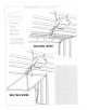
S_ _kL_ i ] _!iii_ __i!_i_iiii_ i!i_:_ii_ _:_!_ _:_'::_s:_'_i SECTgOHAL DOORS ONE PIECEDOORS
Before You Start.,. identify your door •follow specific index for assemblyand installation Sectional D DOt With Curved Track One Piece Door. Jamb Hardware_ Horizontal Track° One Piece Door, No Track. Jamb Hardware,, One Piece Door. No Track, Pivot Hardware, .f UX gx ,,/_, / ,, /il // // DOOR \ DOOR \ \ \ TRACK / // TRACK ! // // DOOR 9 iNSTRUCTiON Assembly INDEX ......... installation ...... COMMON INDEX : JAMB HARDWARE iNSTRUCTION INDEX INSTRUCTION Pg_ 6 Assembly .....
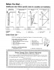
Preparation MAiNTAiN THE VALUEOF YOURGARAGEDOOROPENER MAINTENANCEAGREEMENT Here \ is a comparative Maintenance chart Agreement indicating coverage the warranty for and a Sears Maintenance Agreement .... .................. Coverage AGREEMENT ,' l 1 \ 1) Defective 2) Service Sears Garage tested for Opener Door Openers years of dependable however, may require Sears warranty plus vides from coverage use and from are designed, The only operation service unexpected Agreement
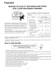
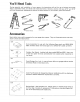
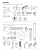
You'll Need Toels During assembly and installation of your opener, the instructions will call for use of various hand tools_ Have a stepladder handy, and those tools illustrated below: Hammer, electric drill (also 3/16" and 5/16" drill bits), screwdriver', adjustable end wrench or socket wrench kit, wire cutters, pliers and hacksaw.. Adjustable End Wrench Pliers Stepladder Wire Socket Cutters Wrench Accessories Sears stocks many useful accessories for your garage door' opener.
Hardware Open the hardware containers and check contents before startingF Rail Assembly Hardware Box Chain Retainer Bracket Trolley Master Rait Link Grease 12) @ Items in this box bly of the nuts, bolts, are actual 2 Lock are for assem- T.
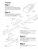
Assembly Reverse Step Switch Cover 1 Open Rail Assembly Hardware Box REMOVE SPROCKET COVER FROM OPERATOR: Place operator on packing material to prevent scratching chassis cover. Remove sprocket cover from top of chassis by unfastening screw as illustrated. DO NOT REMOVE REVERSE SWITCH COVER, Screw Sprocket ASSEMBLE numbers RAIL: as illustrated. seated in square holes surface during Assemble Square the in sections assembly,.
Assembty 5 'i6x_t6 LG BOLT ATTACH ASSEMBLED operator two on packing holes chassis in motor an illustrated, TEE material RAIL to end of avoid Tee rail For convenience, TO OPERATOR: scratching with holes place in operator a support sprocket bracket Fasten Tee rail to operator with screws 5/16 inch by 9/16 inch Tighten securely, ASSEMBLED TEE RAIL WITH TROLLEY Place cover,, Align two under washered 5/I6 NUT SCREWDRIV SPROCKET BRACKET OPERATOR CHASSIS \TROLLEY BRACKET TROLLEY
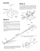
Installation Step 7 TIGHTEN two 5/16 THE CHAIN: Tighten the chain by inch nuts on chain stud de_ignated"inner" adjusting the and "outer" as illustrated,, Chain is propmty tightened when it is approximately 1/2 inch above the base of the Tee rait at its midpoint between idler CAUTION: sprocket Chain and the operator / Keep the chain from twisting as nuts are turned Remove screwdriver or nait from Tee rail Base of Tee Rail REPLACE SPROCKET COVER REMOVED IN STEP 1, Assembly of the garage
Installation POSITION THE OPERATOR: Raise operator onto a stepladder, Open the garage door,, Place a 2x4 on edge along top section door, Rest the Tee rail on the 2x4 as illustrated NOTE: A 2x4 is convenient for establishing an ideal door-torail distance, It is not a necessity where headroom is insufficient,, weight SECURE tration) THE OPERATOR: between operator Measure and joist, distance or other ("L" angles,.
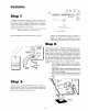
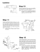
installation Step 1:3 -x / Cotter Pin -- DETERMINE cord DOOR through end through Remove ARM red handle hole plastic LENGTH: Thread and secure with in release arm of trolley, carrying strap from arm to door bracket with 3/8 Straight one end of nylon knot,_ Thread Secure straight with door other a knot inch clevis ti a_m,. Place one end of straight door arm in slot in trolley and fasten with 3/8 inch clevis pin and cotter pin,.
instaJlation COD_ o LABEL CAUTION: SIGNAL CODE LABEL RECEIVER OR ADDITIONAL MUST BE MOUNTED SMALL CHILDREN. OUT PUSH OF THE BUTTON REACH OF INSTALL RADIO RECEIVER: There are installation flanges at both ends of the receiver, Attach the receiver to an interior OPENER TERMINAL BLOCK ooi garage cation wall with the wood screw, s provided.
justment Step 16 ADJUST OPENER ptete up and clown door if LtMITS: Run the opener through a comcycle. Adjustments are not needed when opens and closes door does not completely. close completely, lengthen door arm as required, A,. Run door in UP direction. nut adjustments CAUTION: Disconnect Bo Remove 4 cover ward from C. Adjustments or' down tion),, power screws Do before limit as follows: cover is removed,.
ustment ADJUST DOOR FORCE: Determine that door force is not ex- cessive in down direction.. Grasp the door handle or the bottom of the door as it is about halfway through downward travel. / Normally the door should reverse by this action. If it is hard to hold, or doesn't reverse, loosen the clown screw one turn at a time until the door reverses normally. CLOSE means FORCE ADJUSTMENT SCREW it will not reverse when A. Adjustment door)° labels \ door next opens B Tighten climatic C
One Piece Door Installations One Piece Door° Jamb Hardware° Step 1 H orizonta| Track. Highest Point ofir_ave _ ,,,_. . ....... INSTALL bag will _ DOO\\_\ 5/16" LOCK WASHER /// TRACK DOOR BRACKET: (Hardware in plastic be needed in the following steps). Determine vertical center line of garage door, Position door bracket center-on-center with this line at leading edge of top of door (see illustration), holes.
One Piece Door InstaHiations POSITION A THE OPERATOR: One-Piece Door Without Track: Raise motor end of opener to a height equal to door bracket with door open. Support opener with stepladder. For maximum efficiency, do not secure the operator more than 2 inches higher than this,. B One-Piece Door With Track: Raise motor end of opener to height above and paraflel to zontal tracks.. Support it with stepladder. \\-\\, _ HEADER hori- BRACKET SECURE THE OPERATOR: Measure distance ("L"
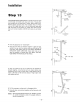
One Piece Door Installations Step 8 SET OPENER LIMITS: (1) Using the radio controls, run trolley back to the "up" limit near motor end of unit, Disconnect electric power, Remove 4 cover screws and slide cover forward from chassis as illustrated_ (2) Adjustments are made by turning large plastic limit nuts up or down a threaded shaft just behind the motor (see illustration), The limit nut retaining bracket which holds the nuts in place must be loosened before nuts can be turned° CAUTION: Do not run opener
One Piece oor Instal Otis ADJUSTMENTS: If, after installation not open or close satisfactorily, follow and 17 on Pages 12 and 13,, of opener, door does adjustment steps 16 P INSTALL REMOTE INSTALLATION LIGHT CE I LING Refer to Step T8, Page 13, INSTALLATION PROCEDURES: (1) Fasten header bracket to a suitable support on ceiling (a 2x4 or 2x6 reinforcing plank nailed to joists, for example), Tile support location should be the most convenient in line with SUPPORT HEADER LENS: PROCEDURES REM
Radio Controls SEARS DiG|TAL The coded signal in Sears Digital is a flat blade screwdriver switch block.
TRANSMITTER RECEIVER r CODE I LABEL SIGNAL CODE LABEL OPENER TERMINAL BELL PUSH BLOCK ooI WIRE i BUTTON RECEIVER TERMINAL BLOCK FLANGE Parts List KEY NO, PART NO, [JESCRIPTION RECEIVER 1 2 IB1436 IA1385S Receiver Receiver case assy.
Wiring & Specifications WIRING DIAGRAM 117 V AC LINE 60Hz NEUT. CONVENIENCE OUTLET(X) WHt _,,C_r I I BUTTON ,'¢7 LAMP DELAY SWITCH YEL CRK. PSC MOTOR fiRK, ..=J RELAY iMPULSE W/THERMAL OVERLOAD j DOWN LIMIT OBSTRUC 0 SWITCH I REVERSE DISABLE CLASS I I BLK q LSW_TCH j t I I UF 24vAC 270 .rz YEL L NOTE : I PARTS(X)AND(Y)ffOT 2 SOME USED _N ALL VERSIONS OF MANUAL RESET MODELS SUTTON HAVE TERMINALS MOTOR Type ..... Speed Volts t/3 ..... Cur_nt run .......
pair Parts Rail AssembBy 2O 10 11_ 12_ _6 4 \ I 8 7 11> ji PartsList / KEY NO. I 2 3 4 5 6 7 8 9 iO II 12 13 14 15 16 17 18 19 20 21 22 23 24 25 26 27 - 21 - PART NO. 146A19 12A129 146A30 133A29 216A26 IA452 171A88 171AZ4 183B35 IA955 146A21 91A7 26A39 I09AII IA1428 IB1435 133A87 2B123 171A191 183B36 171A184 133A28 216A25 12A197 178B22 178B23 12B198 DESCR IPT ION Pin,cotter Bracket,header Pin,clevis,3/Sx3 Nut,3/8-16 Lockv,asher,3i8 Sprocket bracket assy.
Repair Parts ChassisAssemblyParts List KEY f'lO. 3-L L_ .__=___r5_ 2 _.__]5=._ - ,8 58 ....1455 ............ '_-"-_II _<_ ,\',Ltt . t, -_z 53 , 50 _:,#" "' "'I c.,14 E . < 1_. _ ,51,11. =.,.41 ........... \ r _ ' 11 ' I_/'1 _ --I >...... /1_ i .......... i ....._-_,. 1 .:,_ _>7, " /,\ I ;;"=i ..............r......... +'-1] ] ............ .fill <.-"_: t7 I " 18 9 ,, . { :-42 t r16\ ,.,I i 17 <--'f: :, LI.
SAVE-A-CALL BY CHECKINGTHESE BASIC POINTS. INSTALLATION GUARANTEED BY THE INSTALLER.IF IT iS A SELF-INSTALLATION, CORRECTIONSWILL BE MADE ON A CHARGE BASIS. O WHEN DOOR OPENS t Check pushbuttons ding pushbutton(s} staples, etc, WHEN DOOR WILL NOT OPEN WITH TRANSMITTER(S). NOR WALL OR RECEIVER PUSHBUTTONS: 1. Check to be certain that NO LOCKS OR BOLTS are preventing the door from opening, 2 Check for tripped circuit breaker or blown fuse..
HOW TO ORDER REPAIR PARTS The Model Number' will be found on the label attached to the back of the opener.. Always mention the Model Number when requesting service or repair parts for your SEARS ELECTRONIC GARAGE DOOR OPENER° All parts listed herein may be ordered through SEARS, ROEBUCK AND CO. When ordering parts by mail, selling prices will be furnished on request, or parts will be shipped at prevailing prices and you will be billed accordingly.