
Specifications


19
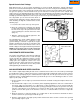
Choke Shaft and Plate
The choke plate is inserted into the air horn of the
carburetor in such a position that the flat surface (if
applicable) of the choke is down. Choke plates will
operate in either direction. Make sure it is assembled
properly for the engine. Test the operation of the choke
and return spring function if equipped (diag. 46).
Always use a new screw(s) when reinstalling the
choke shutter as the screws are treated with dry-type
adhesive to secure them in place.
NOTE: NEVER REUSE OLD SCREWS.
The choke shaft and plate must be in the closed
position prior to tightening the screws. Hard starting
may be due to insufficient choking action because of
a misaligned choke plate. Correct by readjusting the
choke plate to close completely. Note the cutout
position of choke shutter if applicable.
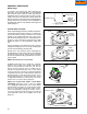
On Walbro LMK and Series 7 carburetors, install the
choke return spring on the choke shaft with the
squared end up and hooked into the notch in the plate.
Work the dust shield up around the spring and insert
the choke shaft into the carburetor body. Rotate the
shaft counterclockwise until the tang on the spring
rests against the left side of the center boss on the
carburetor body (viewed from choke end) . Rotate the
choke shaft approximately 1/4 turn counterclockwise
and insert the choke shutter into the slot in the choke
shaft. Make sure the tabs on the shutter lock the choke
shaft between them. Rotate the shaft and check for
binding, the choke must return to the open position
when released (diag. 47).
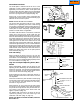
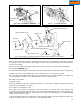
Fuel Inlet Fitting
When installing the fitting, insert the tip into the
carburetor body. Support the carburetor body with a
wood block to avoid damage to other parts. Use a
bench vise or press to install the fitting squarely. Press
it in until it bottoms out (diag. 48).
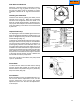
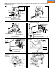
High and Low Speed Adjusting Screw, Main
Nozzle
When reassembling, position the coil spring on the
adjusting screws, followed by the small brass washer
and the O ring seal. Turn the high speed adjustment
screw into the bowl nut and the low speed mixture
screw into the carburetor body (diag. 49).
Some carburetors may have a fixed main mixture or
both a fixed idle mixture and main mixture, and are
not adjustable.
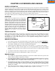
On Series 7carburetors, place the main nozzle spring
into the main nozzle cavity. Apply oil to the main nozzle
"O" ring and push the main nozzle into the cavity
with the "O" ring end in first.
Next install the "O" ring in the main jet cavity. Place
the spring over the shoulder on the main jet and push
the jet into the cavity with the main jet toward the "O"
ring. Place a new gasket on the drain screw and
tighten in position (diag. 50).
On Walbro LMK carburetors, the main jet can be
replaced by pressing it into the center leg of the
carburetor until flush. (diag. 31 page 15).
NOTE: FOR HIGH ALTITUDE JETTING, CONSULT
BULLETIN 110.
50
FLOAT HINGE PIN
NEEDLE &
SEAT
SEAT RETAINING
RING
FLOAT
IDLE RESTRICTION
MAIN JET
MAIN JET SPRING
"O" RING
SPRING
BOWL RETAINER
BOWL
DRAIN
BOWL
MAIN NOZZLE EMULSION
"O" RING POSITIONED IN
GROOVE
GASKET
49
RETAINER NUT
SPRING
"O" RING
BRASS WASHER
HIGH SPEED
ADJUSTMENT
SCREW
48
STRAINER
SOME INLET FITTINGS
PRESS IN PARTIALLY
THEN APPLY
LOCTITE
47
FLAT DOWN
CHOKE PLATE
46
SPRING
HOOKUPS
Þ
Main Menu