Operator’s Manual Model 120000 Model 200000 Power Built 825/850/875/900 Series Intek I/C 825/850/875/900 Series I/C 825/850/875 Series Model 150000 Model 210000 Power Built 1100/1125 Series BRIGGSandSTRATTON.com Power Built 1350/1450 Series Intek I/C 1350/1450 Series I/C 1450 Series Power Built 1500/1575 Series Intek I/C 1500/1575 Series ECopyright Briggs & Stratton Corporation Milwaukee, Wisconsin 53201 U.S.A. Form No. 277040-3/07 Printed in U.S.A.
Thank You for purchasing this quality-built Briggs & Stratton engine. We’re pleased that you’ve placed your confidence in the Briggs & Stratton brand. When operated and maintained according to the instructions in this manual, your Briggs & Stratton product will provide many years of dependable service. This manual contains safety information to make you aware of the hazards and risks associated with engines and how to avoid them. It also contains instructions for the proper use and care of the engine.
Safety . . . . . . . . . . . . . . . . . . . . . . . . . . . . . . . . . . . . . . . . . . . . . . Symbols And Warnings . . . . . . . . . . . . . . . . . . . . . . . . . . . . . . . . . . . . . . . . . . 2 2 5 Operation . . . . . . . . . . . . . . . . . . . . . . . . . . . . . . . . . . . . . . . . . . . 6 10 10 11 11 11 11 12 13 14 14 15 15 Specifications . . . . . . . . . . . . . . . . . . . . . . . . . . . . . . . . . . . . . . 17 Power Ratings . . . . . . . . . . . . . . . . . . . . . . . . . .
Safety Safety Symbols And Warnings The safety alert symbol is used to identify safety information about hazards that can result in personal injury. A signal word (DANGER, WARNING, or CAUTION) is used with the alert symbol to indicate the likelihood and the potential severity of injury. In addition, a hazard symbol may be used to represent the type of hazard.
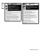
WARNING WARNING When Adding Fuel • Turn engine off and let engine cool at least 2 minutes before removing the gas cap. • Fill fuel tank outdoors or in well-ventilated area. • Do not overfill fuel tank. Fill tank to approximately 1-1/2 inches below top of neck to allow for fuel expansion. • Keep gasoline away from sparks, open flames, pilot lights, heat, and other ignition sources. • Check fuel lines, tank, cap, and fittings frequently for cracks or leaks. Replace if necessary.
WARNING Safety Running engines produce heat. Engine parts, especially muffler, become extremely hot. Severe thermal burns can occur on contact. Combustible debris, such as leaves, grass, brush, etc. can catch fire. • Allow muffler, engine cylinder and fins to cool before touching. • Remove accumulated debris from muffler area and cylinder area. • Install and maintain in working order a spark arrester before using equipment on forest-covered, grass-covered, brush-covered unimproved land.
Features A. Spark Plug O B. Air Cleaner (flat or oval) I A C. Choke Control Lever J Features D. Fuel Shut-off Valve E. Rewind Handle F. Finger Guard B G. Throttle Control Lever H. ON/OFF Switch (rewind start models) C I. Fuel Tank and Cap D J. Extended Dipstick (if equipped) K. Short Dipstick (if equipped) E L. Oil Drain Plug Q M. Oil Fill Cap F P N. Engine Identification (located on cover) Model Type Code G O.
Operation Oil Capacity CAUTION Model 120000 and 150000 series engines: 20 ounces (0.6 liter). Model 200000 and 210000 series engines: 28 ounces (0.8 liter). If this engine is equipped with a gear reduction unit, the gear reduction case must be filled with oil prior to operating the engine. See “How To Change The Gear Reduction Oil” in the Maintenance Section. Oil Recommendation Operation • Do not use special additives. • Choose a viscosity from the following chart.
Extended Dipstick (Figure 3) 1. Remove the dipstick (B) and wipe with a clean cloth. 2. Insert and tighten the dipstick. 3. Remove the dipstick and check the oil level. Make sure the oil is at the FULL mark (C) on the dipstick. 4. To add oil, pour the oil slowly into the engine oil fill (D). DO NOT OVERFILL. After adding oil, wait one minute and then recheck the oil level. 5. Fill to the FULL mark (C) on the dipstick. 6. Replace and tighten the dipstick.
How To Start The Engine CAUTION This engine was shipped from the factory without oil. If you start the engine without oil, the engine will be damaged beyond repair and will not be covered under warranty. ST O P D Figure 7: Throttle Control Lever CAUTION Operation Some engines may be equipped with OIL GARD®. The OIL GARD® is intended to warn the operator that the engine is low on oil. Always check oil level before starting.
7. Electric Start -- Push in the safety key (F). Push the ON/OFF switch (B) to the ON position. When the engine starts, release the ON/OFF switch (Figure 11). B F E Figure 11: Electric Start operate with the throttle in FAST Figure 10: Rewind Start position. NOTE: When starting a warm engine after a short shutdown, leave the choke lever in the RUN position. If the engine fails to start, follow the starting instructions beginning with step 3. If assistance is needed, see the “Troubleshooting” Chart.
Maintenance Maintenance Chart Procedure 8 Hours or Daily 25 Hours 50 Hours 100 Hours 100-400 Hours Check Oil Level Clean Engine of Debris Service Air Cleaner Pre-Cleaner (if equipped) † Replace Air Cleaner Cartridge (if not equipped with pre-cleaner) † Change Oil n Inspect Muffler And Spark Arrester (if equipped) Replace Air Cleaner Cartridge (if equipped with pre-cleaner) Maintenance Change Oil in Gear Reduction (if equipped) Inspect/Replace Spark Plug Replace Fuel Filter (if equipped) Clean Air Co
CAUTION All the components used to build this engine must remain in place for proper operation. Emissions Control Maintenance, replacement, or repair of the emissions control devices and systems may be performed by any non-road engine repair establishment or individual. However, to obtain no charge repairs under the terms and provisions of the Briggs & Stratton warranty statement, any service or emissions control part repair or replacement must be performed by a factory authorized dealer.
How To Change The Oil G Remove Oil (Figure 16) 1. With engine off but still warm, disconnect the spark plug wire and keep it away from the spark plug. 2. Remove the oil drain plug (F). Drain the oil into an appropriate receptacle. Note: Some of the various types of oil drain plugs (G) are shown in Figure 16. F Figure 16: Oil Drain Plug 3. Replace and tighten the oil drain plug. Before adding oil A Maintenance • Place engine level. Figure 17: Oil Fill Cap • Clean the oil fill area of any debris.
How To Service The Air Filter CAUTION Do not use pressurized air or solvents to clean the filter. Pressurized air can damage the filter and solvents will dissolve the filter. 4. Install the new cartridge and pre-cleaner (if equipped) into the base and onto stud (J). Make sure cartridge fits securely into base (G). 5. Install air filter cover and secure with knob. Make sure the knob is tight. G B WARNING Gasoline and its vapors are extremely flammable and explosive.
How To Change The Gear Reduction Oil (Figure 23) Maintenance Change the oil in the gear reduction unit every 100 hours. The gear reduction unit is an optional feature that is not included on all models. If your engine is equipped with a gear reduction unit, service as follows. 1. Remove the oil drain plug (A) and drain the oil into an appropriate receptacle. 2. Install and tighten the oil drain plug. 3. Remove the oil fill plug (B) and the oil level plug (C). 4.
Clean Air Cooling System (Figure 25) CAUTION Keep linkage, springs and controls (B) clean. Keep the area around and behind the muffler (C) free of any combustible debris. Do not use water to clean the engine. Water could contaminate the fuel system. Use a brush or dry cloth to clean the engine. C WARNING Running engines produce heat. Engine parts, especially muffler, become extremely hot. Severe thermal burns can occur on contact. Combustible debris, such as leaves, grass, brush, etc. can catch fire.
Troubleshooting PROBLEM Engine g will not start Engine g difficult to start or E i runs erratically Engine ti ll or CAUSE Out of fuel Add clean fresh fuel. Carburetor flooded Move the choke control lever to the RUN position. Then follow the starting procedure until the engine starts. Low oil Check oil level. Note: On some engines, if the oil pressure drops below 4-6 psi (0.2-0.4 kg/cm2), an oil pressure switch will either activate a warning light or stop the engine.
Specifications Common Service Parts n Engine Specifications Model: Displacement: Bore Stroke 120000 12.48 cu in (206 cc) 2.672 in (68 mm) 2.204 in (56 mm) Model: Displacement: Bore Stroke 150000 15.22 cu in (249 cc) 2.970 in (75.44 mm) 2.200 in (56 mm) Model: Displacement: Bore Stroke 200000 18.64 cu in (305 cc) 3.120 in (79.23 mm) 2.438 in (61.67 mm) Model: Displacement: Bore Stroke 210000 20.85 cu in (342 cc) 3.300 in (83.81 mm) 2.438 in (61.
BRIGGS & STRATTON ENGINE OWNER WARRANTY POLICY Effective 12/06 LIMITED WARRANTY Briggs & Stratton Corporation will repair or replace, free of charge, any part(s) of the engine that is defective in material or workmanship or both. Transportation charges on product submitted for repair or replacement under this warranty must be borne by purchaser. This warranty is effective for and is subject to the time periods and conditions stated below.
Emissions Control System Warranty Statement Briggs & Stratton Corporation (B&S), the California Air Resources Board (CARB) and the United States Environmental Protection Agency (U.S. EPA) Emissions Control System Warranty Statement (Owner’s Defect Warranty Rights and Obligations) California, United States and Canada Emissions Control Defects Warranty Statement below. If any covered part on your engine is defective, the part will be repaired or replaced by B&S. The California Air Resources Board (CARB), U.
Look For Relevant Emissions Durability Period and Air Index Information On Your Engine Emissions Label Engines that are certified to meet the California Air Resources Board (CARB) Tier 2 Emissions Standard must display information regarding the Emissions Durability Period and the Air Index. Briggs & Stratton makes this information available to the consumer on our emissions labels. The engine emissions label will indicate certification information.
Models 120000 150000 200000 210000 Engine Specifications Engine Specifications Model: Displacement: Bore Stroke 120000 12.48 cu in (206 cc) 2.672 in (68 mm) 2.204 in (56 mm) Model: Displacement: Bore Stroke 150000 15.22 cu in (249 cc) 2.970 in (75.44 mm) 2.200 in (56 mm) Model: Displacement: Bore Stroke 200000 18.64 cu in (305 cc) 3.120 in (79.23 mm) 2.438 in (61.67 mm) Model: Displacement: Bore Stroke 210000 20.85 cu in (342 cc) 3.300 in (83.81 mm) 2.438 in (61.