truction anu ® 6-1/8-in. Wide 1-1/2 Horsepower (continuous duty) 5000 Cutterhead R.P.M. (no load speed) / Mode_ No. 152.217050 C S FOR YOUR OWN SAFETY; Read and foUlow all of the Safety and Operating Instructions before Operating this Table Saw. Customer Helpline 1-800-897-7709 PRease have your Model No. and SedaR No. availabUe. Sears, Roebuck Part No. 0R92216 and Co., Hoffman Estates, JL 60179 U.S.A.
SECTION PAGE Warranty.............................................................................................................................................................. 2 ProductSpecifications .......................................................................................................................................... 2 Safetyinstructions...............................................................................................................................................
GENERAL SAFETY INSTRUCTmONS Operating a Jointer/Haner can be dangerous if safety and common sense are ignored, The operator must be familiar with the operation of the tool Read this manuaU to understand this Jointer/Haner, DO NOT operate this Jointer/Haner if you do not fully understand the Hmitations of this tool DO NOT modify this Jointer/Haner in any way, BEFORE READ the entire Owner's Manual, LEARN how to use the tool for its intended applications, GROUND ALL TOOLS, If the tool is supplied with a 3
21. EACH AND EVERY TmME,CHECK FOR DAMAGED PARTS PRmORTO USmNGTHE TOOL. Carefully check aH guards to see that they operate properUy, are not damaged, and perform their intended functions. Check for alignment, binding or breaking of moving parts. A guard or other part that is damaged shouUd be immediateUy repaired or repUaced. 22. CHILDPROOF THE WORKSHOP AREA by removing switch keys, unplugging tools from the electrical receptacles, and using padlocks.
THiS TOOL MUST BE GROUNDED WHILE iN USE TO PROTECT THE OPERATOR FROM ELECTRIC SHOCK.
it is aUsonecessary to repUace the 120 voUtpUug,supplied with the motor, with a UL/CSA Listed pUugsuitabb for 240 voUts and rated current of the jointer/pUaner, Contact a bcaU qualified eUectdcian for proper procedures to install the pUug,The jointer/pUaner must compUy with aH bcaU and nationaU eUectdcaUcodes after the 3, KEEP cutterhead knives sharp and free of all rust and pitch, 4, BEFORE starting machine, check cutterhead guard to make sure it is not damaged and operates freely, 240 voUtpUugis inst
19, DONOTattemptto performanabnormalor littleusedoperation withoutstudyandtheuseofadequateholddown/push blocks,jigs,fixtures,stops, pushblocks,etc, 20, SHUTOFFpowerbeforeadjustingjointer, 21, DISCONNECT Jointer/Haner frompowersource beforeservicinganddean themachinebefore havingit, 22, MAKESUREtheworkareais cleanbeforehaving themachine, 23, SHOULDanypartofyourjointerbemissing,damaged,or failinanyway,or anyebctdcalcomponentsfailto performproperly,shutoffswitchand removeplugfrompowersupplyoutbt,Replace missin
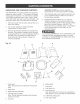
UNPACKUNG AND CHECKUNG CONTENTS The Jointer/Haner is a heavy machine, two peopb are required to unpack and lift it, This machine will require some amount of assembly, You will need for assembly a #2 Phillips screwdriver, 8mm, lOmm, 14mm, 16mm, 17mm and 19mm open end wrench (not included), Hex wrenches 2,5mm, 3mm, 4mm and 6mm are provided, 1, Remove all parts from the carton and lay them on a clean work surface, 2, Two or more people are required to lift the Jointer/Planer out of the carton, 3, Remove
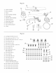
Fig. 2-2 12 12, Jointerassembly 13, Motorassembly 14, Fence 15, Fencebevelingassembly 16, Motorpulley 17, ON/OFFswitchassembly 18, Cutterhead guard 19, Infeedtablehandle 18 17 20, Fencehandles(2) 21, Rearcutterhead guard 22, V-Belt 22 20 21 Fig.
Fig.
Fig.
Fig.
Fig.
BELT ASSEMBLY GUARD DO NOT assembb the Jointer/Haner until you are sure the power switch is in the "OFF" position and the power cord is disconnected from the power source, DO NOT assembb the Jointer/Haner until you are sure the power switch is in the "OFF" position and the power cord is disconnected from the power source, Fig. 8-1 A AND SWITCH ASSEMBLY Fig.
FENCE ASSEMBLY DO NOT assemble the Jointer/Haner until you are sure the power switch is in the "OFF" position and the power cord is disconnected from the power source, Fig. 10-1 \ K J G H B F E C G Loosen set screw (A) on fence bevel assembly (B) and remove the cam lock shaft (C), Remove the bolt damp (D), M12 fiat washer (E) and M12 Nylock hex nut (F) from cam lock shaft (C), See Figure 10-1, 5, 2, Assemble the handles (G) into the fence (H) and cam lock shaft, 3, Remove four M8 x 14mm hex s
Fig. 10-5 Fig.
CUTTERHEAD GUARD ASSEMBLY FRONT AND BACK PANEL ASSEMBLY DO NOT assembie the Jointer/Pianer until you are sure the power switch is in the "OFF" position and the power cord is disconnected from the power source, DO NOT assembie the Jointer/Pianer until you are sure the power switch is in the "OFF" position and the power cord is disconnected from the power source, Fig.
CAUTION • AseparateeUectdcaU circuitshouUd be usedforyour Jointer/Haner. TheJointer/Haner comespre-wired for 120-voUt use.ThecircuitshouUd notbe Uess than#14 AWGwireandshouUd be protected witha 15-amp timeUag fuse. Havea quaUified eUectdcian repairor repUace damagedor worncordimmediateUy. Beforeconnecting themotorto thepowerHne,make certaintheswitchis in the"OFF"positionandbesure thattheeUectric currentis ofthesamecharacteristics asthe motornamepUate. AHHneconnections shouUd makegoodcontact.
THERMAL°OVERLOAD PROTECTION CAUTION: 1/2" DEPTH-OF-CUT iS ONLY USED iN RABBET-CUTTING OPERATIONS.
2, Standing in front of the jointer, grasp the top of the fence between the front support brackets (C) and slide the fence to the desired position, 3, Tighten cam handle, Make sure the cutterhead guard (D) returns and rests against the fence, If not see CUTTERHEAD GUARD ASSEMBLY section in assembly instruction for setup procedure, TILTING G 4, THE FENCE Turn the power switch OFF and unplug the power cord from its power source prior to performing any maintenance or adjustments, H The fence can tilt
45 Degree Out Positive Stop Adjustment 45 Degree Fig. 17-2 in Positive Stop Adjustment Fig. 17-3 H A F 1. To set fence 45 degree in to the table surface, first make sure the 90 degree stop knob (A) is pulled out. See Figure 17o3. 2. Loosen the bevel lock handle (D) and tilt the fence forward and against the 45 degree in positive stop screw (H). Note: This positive stop screw does not touch the fence on the head side of the screw, but on the threaded end.
KNIFE ADJUSTMENTS Fig. 18-2 in order to do accurate work, the knives must be exactly bveU with the outfeed tame. See Figure 18-1. H Fig. 18-1 C B / F A / D G E 4, 8, To avoid serious injury, disconnect jointer/planer from power source, CAUTION: The knife edges are sharp. Do not touch or you may be cut. 6, 1, Lower infeed table (A) and remove cutterhead guard, See Figure 18-1, 2. Set a straight edge (B) on the outfeed table (C), extending over center of the cutterhead (E). See Figure 18-1.
KNIFE REMOVAL KNIFE REPLACEMENT CAUTION: To avoid cutting yourself, be very careful when removing, replacing and resetting knives, Fig. 19-1 1/16" of Knife I_ Protrusion from Cutterhead 1/16" B B 1 B A A To avoid serious injury, disconnect jointer/planer from power source. C CAUTION: The knife edges are sharp. Do not touch or you may be cut. B Knives (A), Knife-Locking Bars (B), and Knife-Locking Screws (C) must be assembled paraHe_ to the face (B) of the cutterhead groove. 1.
ADJUSTING TABLE GUBS CHANGUNG Gibs are internai mechanisms that take up any piay between the base and the infeed and outfeed tames. Precise gib adjustment is done at the factory and shouid not require any further adjustments. However, if adjustments are required, phase follow instructions bebw. 2, 3, 4, 5, 6. A A VOLTAGE MAKE CERTAIN the Jointer/Haner is disconnected from the power source before working on motor. Have a certified electrician make all electrical connections.
Useofthistoolcangenerateanddisbursedustor other airborneparticles,includingwooddust,crystalline silica dustandasbestosdust,Directparticlesawayfromface andbody,Alwaysoperatetoolinwellventilatedarea andprovideforproperdustremoval,Usedustcollectionsystemwhereverpossible,Exposuretothedust maycauseseriousandpermanent respiratory or other injury,includingsilicosis(a seriouslungdisease), cancer,anddeath,Avoidbreathingthedust,andavoid prolonged contactwithdust,Allowingdusttoget into yourmouthor eyes,or layonyourski
Repairsto theJointer/Planer shouldbeperformedby trainedpersonnel only,ContactyournearestSears ServiceCenterforauthorized service,Unauthorized repairsor replacement withnon-factory partscould causeseriousinjurytotheoperatoranddamageto the Jointer/Planer, tenance to keep your table saw looking new, Cleaning and waxing the cast iron surfaces on a regular maintenance schedule is recommended as follows: To ctean and maintain the unpainted cast iron surfaces: Apply a heavy coat of WD-40 onto the unpainted cast i
TOPREVENT iNJURYTOYOURSELF or damageto theJointer/Haner, turntheswitchtothe"OFF"positionand unpUug thepowercordfromtheeUectdcaU receptacle beforemakinganyadjustments, PROBLEM UKELY Motor does not start 1. Switch not pressed in far enough switch in the "OFF" position. 2. Defective switch. 3. Defective Motor stalls (resulting in bmown fuses or tripped circuit breakers) SOLUTION CAUSE(S) or 1: Depress switch in 1/2 inch or make sure switch "ON" position. 2. Have switch replaced. motor. 3.
6-1/8qN. JOmNTER/PLANER PARTS UST When servicing, use only CRAFTSMAN product damage, MODEL NO. 152.217050 replacement parts, Use of any other parts may create a HAZARD or cause Any attempt to repair or replace electrical parts on this Jointer/Planer may create a HAZARD unless repair is done by a qualified service technician, Repair service is available at your nearest Sears Service Center, Always order by PART NUMBER, not by key number, KEY NO. PART NO. DESCRiPTiON KEY NO. PART NO.
6-1/8-mN. JOmNTER/PLANER PARTSLmST MODELNO.152.217050 KEY NO, PART NO, DESCRIPTION QTY, KEY NO. PART NO.
6-1/8qN.JOmNTER/PLANER PARTSUST MODELNO.152.217050 85 86 -- 87 88 /.
6-1/8qN. JOINTER/PLANER PARTS UST MODEL NO. 152.
6-1/8qN.JOmNTER/PLANER PARTSUST MODELNO.152.
_n ® 6ol/8 pumg. de ancho 1o1/2 cabalio de fuerza (servicio continuo) Cabezam de corte de 5000 R.P.M. (sin vemocidad de carga P m No. de Mode_o 152.217050 C S PARA SU SEGURIDAD PERSONAL; Lea y obedezca todas las lnstrucciones Seguddad y Funcionamiento antes de accionar esta MacNmbradora/Cepilladora. de Linea de Ayuda al Cliente 1°800°897°7709 Sirvase tenet listo su No, de Modelo y No, de Serie Sears, Roebuck and Co., Hoffman Estates, No. de Pieza OR92216 33 JL 60179 U.S.A.
SEOCION PAGINA Garantia ............................................................................................................................................................................. Especificaciones del Producto ....................................................................................................................................... lnstrucciones lnstrucciones de Seguddad ......................................................................................................
INSTRUCCIONES DE SEGURIDAD GENERALES 9, El funcionamiento de una Machimbradora/Cepilladora puede resultar peligroso si se hace caso omiso de la seguridad y del sentido com0n. El operario debe estar familiarizado con eI funcionamiento de la herramienta. Lea este manual para entender su Machimbradora/Cepilladora. NO OPERE esta Machimbradora/Cepilladora si no entiende a cabalidad las limitaciones de dicha herramienta. NO realice modificaciones de cualquier tipo a esta Machimbradora/Cepilladora.
21: REVISE SI HAY PIEZAS DANADAS ANTES DE OADA USO DE LA HERRAMIENTA. Revise todos los protectores cuidadosamente para comprobar que funcionan correctamente y que no estan dahados, y que reatizan sus funciones diseSadas correctamente. Revise el alineamiento, la fijaci6n o Ia ruptura de bs piezas en movimiento. Cualquier protector u otra pieza que se encuentre daSada debe repararse o reemplazarse inmediatamente.
USE SOLO UNA EXTENSKSN EL¢:CTR_CA DE TRES HJLOS CON ENCHUFE DE CONEXJON A TIERRA DE TRES MACNOS Y RECEPTACULO DE TRES MACNOS QUE ACEPTE EL ENCNUFE DE LA NERRAMIENTA. ESTA HERRAM_ENTA DEBE ESTAR CONECTADA A TIERRA DURANTE EL USO PARA PROTEGER AL OPERAR_O CONTRA LOS CHOQUES ELC;CTR_COS. REPONGA UN CORDON DANADO tNMEDJATAMENTE. EN EL CASO DE UN MALFUNCIONAMIENTO O AVERiA, Ia conexi6n a tierra ofrece ei trecho de menor resistencia para Ja corriente electrica y reduce el riesgo de choque el6ctrico.
Tambien resulta necesario reemplazar el enchufe de 120 voltios suministrado con el motor por un enchufe de clasificaci6n UL/CSA adecuado para el funcionamiento a 240 voItios y Ia corriente clasificada de Ia machimbradora / cepilIadora. Comun[quese con un electricista local competente para los procedimientos correctos para instaiar e! enchufe. La machimbradora / cepilladora debe cumplir con todos Ios c6digos eIectricos Iocales y nacionales tras la instaIaci6n del enchufe de 240 voltios.
19. NO trate de realizar una operaci6n anormal o poco utilizada sin e! estudio debido y e! uso de retenes/ bloques de empuje, montaje, fi]aciones, topes, etc. [ncluyendo silicosis (una enfermedad pulmonar grave), cancer y la muerte. Evite aspirar el polvo y evite el contacto prolongado con el polvo. El permitir que el polvo penetre su boca u ojos, o que permanezca sobre su piel, podra promover la absorci6n de materiales nocivos.
DESEMBALAJE Y REVISION DEL CONTENIDO PRECAUCK_N: NO UTlUCE acetona, gasolina ni diJuyente de laca para quJtar los revestimientos protectivos. 4. La Machimbradora / Cepilladora es una maquina pesada. Se requieren dos personas para desembalarla y Ievantarla. Esta maquina requerir_, cierta cantidad de ensamblaje. Para reaJizar el ensamblaje necesitara un destornillador Phillips #2 y Jlaves de boca de 8 ram, 10 mm, 14 mm, 16 mm, 17 mm y 19 mm (no incluidas). Se suministran Jlaves hexagonales de 2.
Fig. 2-2 12 12. EnsambIado de machimbradora 13. EnsambIado del motor 14, Gufa 15. Ensamblado gu[a de biselado de la 16. Polea del motor 17. Ensamblado del interruptor de ENCENDDO / APAGADO 18. Protector del cabezal de corte 19. Asidera de Ia mesa de avance directo 18 17 20. Asideras de Ia gu[a (2) 22 21. Protector trasero del cabezal de corte 22. Correa en "V" 20 21 Fig. 2-3 23. Pies niveJadores con tuerca hexagonaJ (4) 24. TornilIo de cabeza hexagonal 3/8-16 x 1 pulg. (4) 25.
3 7 10 12 13 1. Mesa de avarice de salida 10. Escala de profundidad de corte 2, Gu[a 11. Bloques de empuje 3. Agarradera de cierre de la desiizadera de la gufa 12. Portador de bloque de empuje 13. Estante encerrado 4. Agarradera de la gu(a 5. Bot6n de restablecimiento termico 14. Pies niveladores 6. Bot6n de ENCENDDO/APAGADO 15. Salida del Conducto de PoNe 7.
Fig. 4-2 I PARA EVJTAR HERJDAS GRAVES Y DANO A LA MACHII_BRADORA 1 CEPILLADORA: 1. NO monte !a machimbradora / cepii!adora hasta que este seguro de que la herramienta NO esta enchufada. 2, NO monte !a machimbradora / cepiHadora hasta que este seguro de que eI interruptor de energfa se encuentre en la posici6n de "APAGADO". 3. NO monte !a machimbradora / cepii!adora hasta que haya le[do y entendido este Manual de hstrucciones cabalmente. 4. NO monte !a machimbradora o si estan daRadas.
Fig. 4-4 ENSAMBLADO DEL MOTOR P NO monte Ia Machimbradora/Cepilladora hasta que este seguro de que el interruptor de energ[a se encuentre en la posici6n de APAGADO y el cord6n de energ[a este desconectado de la fuente de energ[a. N A 6. Coloque el ensamblado del estante sobre su ensamblado det panel lateral izquierdo (A). Ver Ia figura 4-4. 7. Coloque el conducto de polvo (M) entre las pestaSas (N) de la ptaca superior. Ver las Figuras 4-3 y 4-4.
Fig. 5-3 Co!oque la Machimbradora / Cepilladora (A) sobre el estante (B) de manera que los tres gorrones situados per debajo de la base de Ia machimbradora queden alineados con las tres ranuras en la placa superior deI estante. Ver la Figura 6-1. 1. K L Afiance la machimbradora al estante con tres arandeIas planas M10, arandelas de cierre M10 y tuercas hexagonales M10. Aviso: Se puede conseguir acceso a dos de los gorrones en la base de Ia machimbradora dentro deI estante.
ENSAMBLADO DE LA CORREA ENSAMBLADO DEL PROTECTOR EL INTERRUPTOR NO monte la Machimbradora / Cepilladora hasta que este seguro de que el interruptor de energ[a se encuentre en Ia posici6n de APAGADO y eI cord6n de energ(a este desconectado de la fuente de energ[a. Fig. 8-1 Y NO monte Ia Machimbradora / Cepilladora hasta que este seguro de que el interruptor de energ[a se encuentre en la posici6n de APAGADO y el cord6n de energ[a este desconectado de Jafuente de energ[a. A Fig.
ENSAMBLADO DE LA GUiA Fig. 10-3 NO monte la Machimbradora / Cepilladora hasta que este seguro de que el interruptor de energfa se encuentre en Ia posici6n de APAGADO y eI cord6n de energfa este desconectado de la fuente de energfa. \ \\ \ Fig. 10-1 K G H B F E C G Afioje el torni!lo de fijaci6n (A) sobre ei ensamblado de biselado de la gufa (B) y quite el eje del cierre de Ievas (C).
Fig. 10-5 Fig. 10-7 °E /+ 7. Vuelva a ensamblar el eje de cierre de Ievas (C) desmon+ tado en el PASO 1. Aseg0rese de cotocar la abrazadera de pernos (D) sobre el eje de[ cierre de levas seg0n Io [Iustra la Figura 10-5. No monte Ia arandeta plana M12 (E) y la tuerca hexagonal Nylock M12 (F) en este momento. 8. Apriete el torn[llo de fijaci6n (A) hasta que se detenga, luego retroceda 1/2 vuelta. Ver la Figura 10-1.
ENSAMBLAJE DEL PROTECTOR CABEZAL DE CORTE DEL ENSAMBLAJE DELANTERO DE LOS PANELES Y POSTERIOR NO monte la Machimbradora / Cepilladora hasta que este seguro de que el interruptor de energfa se encuentre en Ia posici6n de APAGADO y el cord6n de energ[a este desconectado de la fuente de energ(a. NO monte Ia Machimbradora / CepiIladora hasta que est6 seguro de que el interruptor de energfa se encuentre en la posici6n de APAGADO y el cord6n de energfa este desconectado de Ia fuente de energ[a= Fig.
PRECAUCI6N Debe utilizar un circuito electrico aparte para su Machimbradora / Cepilladora. La Machimbradora / Cepilladora viene cableada de antemano para el uso a 120 voltios. El circuito no debe ser menor que un alambre de #14 AWG y debe estar protegido por un fusible de retardaci6n de 15 amperios. 2. Para encender Ia Machimbradora / CepilIadora, oprima el bot6n verde de ENCENDIDO (B) una mitad de pulgada.
PRECAUCI6N: LA PROFUNDIDAD DE CORTE DE 1/2 PULG° SOLO SE UTIUZA EN LAS OPERACIONES DE CORTE DE ALEFRJZ° PROTECCION CONTRA SOBRECARGAS TERMICAS Gire el interruptor de energfa a la posici6n de APAGADO y desenchufe el cord6n de energfa de su fuente de energ[a antes de realizar cualquier mantenimiento o aiuste. Asegurese de que el bot6n de APAGADO se haya oprimido antes de pulsar el bot6n de restablecimiento sobrecarga termica. 3.
2. De pie frente a Jamachimbradora, agarre Ia parte superior de la gufa entre los soportes de apoyo delanteros (C) y deslice Ia gufa a Ia posici6n deseada. 3. Apriete Ia agarradera de levas. AsegOrese de que el protector deJ cabezal de corte (D) regrese y descanse contra la gufa. Si no, pase a Ia secci6n ENSAMBLAJE DEL PROTECTOR DEL CABEZAL DE CORTE en las instrucciones de ensamblaje para el procedimiento de ensamblaje. INCLINANDO G 4. 5. 6.
Ajuste de Parada hacia Afuera de 45 Grados Positivos A]uste de Parada hacia Adentro Fig. 17-2 de 45 Grados Positivos Fig. 17-3 H A F D 1. Para fijar Ia gu[a a 45 grados hacia adentro contra Ia superficie de Ia mesa, aseg0rese primero de que se haya extra(do Ja perilla de parada de 90 grades (A). Vet Ja Figura 17-3. 2. Afloje la agarradera de cierre de biselado (D) e incline Ia guia hacia adelante y contra el torniIIo de parada positiva de 45 grades hacia adentro (H).
AJUSTES DE CUCHILLAS Fig. 18-2 Para poder reaHzar un trabajo certero, Has cuchHHas deben estar niveHadas exactamente con Hamesa de avarice de saHda. Ver Figura H 18-1. Fig. 18-1 D D G E Para evitar heridas graves, desconecte cepilladora de la fuente de energ[a. 4. S[ una cuchiila (D) se encuentra baja, gire los tornillos de enclavamiento de cuchiIIas (G) en el sentido de las agujas deI reIoj una mida de vuelta con una IIave de boca de 8 mm (no incluida).
EXTRACCK)N DE CUCHILLAS REEMPLAZO PRECAUClON: Para prevenir cortaduras, se debe tener cuidado ai quitar, reempJazar y recolocar las cuchiJJas. DE CUCHILLAS Fig. 20-1 Fig. 19-1 1/!6 putg. de tas cuchittas F de proyecci6n del cabezal de corte 1/16" B D 1 D A A Para prevenir heridas graves, desconecte cepilladora de Jafuente de energ[a. C PRECAUOION: Los bordes de las cuchiIIas son fiIosos. Evite tocados para prevenir cortaduras.
AJUSTANDO DE AJUSTE LAS CORREDERAS CAMBIANDO Las correderas de ajuste con mecanismos internes que elimP nan cualquier holgura que pueda existir entre la base y Ias mesas de alimentaci6n y avance de salida. El ajuste precise de Ias correderas de ajuste se Ileva a cabo en la fabrica y no debe requerir ajustes adicionabs.
El use de esta herramienta puede generar y dispersar polvo u otras part[culas aereas, incluyendo polvo de madera, polvo de sflice cristalino y polvo de asbesto. Aleje las part[culas del rostro y deI cuerpo. Opere siempre la herramienta en una zona que goce de buena ventilaci6n y proporcione Ia remoci6n correcta del polvo. Utilice un sistema de recolecci6n de polvo siempre que sea posible.
Las reparaciones a Ia Machimbradora/Cepilladora deben ser realizadas por personal capacitado solamente. Comunfquese con su Centre de Servicio Sears mas cercano para el servicio autorizado. Las reparaciones o los reempIazos desautorizados con piezas que no son de fabrica pueden resultar en heridas graves al operario y dafio a la Machimbradora/ Cepilladora. mantenimiento rutinario para conservar su sierra de mesa come nueva.
PARA PREVENJR LAS HERIDAS A Si MISMO o eI daSo a la machimbradora/cepiiladora, gire el interruptor a la posici6n de "APAGADO" (OFF) y desenchufe el cord6n de energ(a del tomacordentes antes de realizar cualquier ajuste= PROBLEMA CAUSA 0 CAUSAS El motor 1, Interrupter no presionado suficientemente hacia el fondo, o interrupter en la posicion de APAGADO, 1. Presione el interrupter una mitad de pulgada o aseg0rese interrupter este en la posici6n en ENCENDIDO. 2. Capacitor defectuoso, 3, Motor defectuoso.
Your Home 'i'i'i'i'i'i'i'i'i'i'i'i'i'i'i'i'i For repair-in your home-of all major brand appliances, lawn and garden equipment, or heating and cooling systems, no matter who made it, no matter who sold it! iiiiiiiiiiiiiiiiiii iiiiiiiiiiiiiiiiiii iiiiiiiiiiiiiiiiiii iiiiiiiiiiiiiiiiiii iiiiiiiiiiiiiiiiiii iiiiiiiiiiiiiiiiiii iiiiiiiiiiiiiiiiiii iiiiiiiiiiiiiiiiiii iiiiiiiiiiiiiiiiiii iiiiiiiiiiiiiiiiiii iiiiiiiiiiiiiiiiiii iiiiiiiiiiiiiiiiiii iiiiiiiiiiiiiiiiiii iiiiiiiiiiiiiiiiiii iiiiiiiiiiiiiiiiiii iiii