
Operating instructions

CAUTION
• AseparateeUectdcaUcircuitshouUdbeusedforyour
Jointer/Haner.TheJointer/Hanercomespre-wiredfor
120-voUtuse.ThecircuitshouUdnotbeUessthan#14
AWGwireandshouUdbeprotectedwitha 15-amp
timeUagfuse.
Havea quaUifiedeUectdcianrepairorrepUacedam-
agedorworncordimmediateUy.
Beforeconnectingthemotorto thepowerHne,make
certaintheswitchisinthe"OFF"positionandbesure
thattheeUectriccurrentisofthesamecharacteristics
asthemotornamepUate.AHHneconnectionsshouUd
makegoodcontact.
RunningonUowvoUtageorUongextensioncordswHU
damagethemotor.
STARTING AND STOPPING
2. To turn the Jointer/Haner on, press the green "ON"
button (B) in one-half inch. Note: There is a safety
feature on the switch to insure that the switch must
be completely pressed before the motor will start.
3. To turn the Jointer/Haner off, press the large red
"OFF" paddle (C) or lift the paddle and press direct°
ly on the red "OFF" button (D). See Figure 13-1
and 13-2.
LOCKING SWITCH IN THE "OFF" PosmoN
CHILDPROOF THE WORKSHOP AREA by removing
switch keys, unplugging tools from the electrical recep-
tacles, and using padlocks.
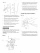
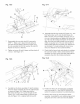
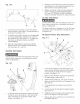
Fig. 13-2
,, DO NOT expose the Jointer/Haner to rain or operate
it in damp locations,
MAKE SURE all parts have been assembled correctly
and are in working order,
,, KEEP table surfaces clear of tools and debris before
starting,
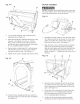
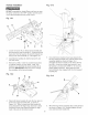
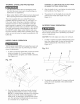
Fig. 13-1 A
B
r
C
1. The ON/OFF switch (A) is located on the post over
the infeed table. See Figure 13-1.
E
C
D
1. When the Jointer/Planer is not in use, the "ON"
button (B) should be locked so that it cannot be
started. See Figure 13o2.
2. Using the padlock (E) included with your Jointeri
Planer, lift the red "OFF" paddle (C) and place the
padlock through the holes in the side of the "ON"
button and then lock the padlock. Make sure keys
have been removed from padlock and placed
where no children can get them.
3. To use the Jointer/Planer, unlock and remove the
padlock from the "ON" button.
18