_truction anu 1 Horsepower (continuous duty) 2 Horsepower (maximum developed) 9°Speed, Step Pulley 150 - 2200 R.P.M. Drill Speed Range iLL P ESS Model No. 152.229020 C CAUTION: FOR YOUR OWN SAFETY; Read and follow all of the Safety and Operating Instructions before Operating this DdH Press. Customer Helpline 1-800-897-7709 PRease have your Model No. and SedaR No. availabUe. Sears, Roebuck and Co. Hoffman Estates, JL 60179 U.S.A. Part No.
SECTmON PAGE Warranty.............................................................................................................................................................. 2 ProductSpecifications .......................................................................................................................................... 3 Safetymnstructions ...............................................................................................................................................
20qn.
GENERAL SAFETY iNSTRUCTiONS Operating a drill press can be dangerous if safety and common sense are ignored, The operator must be familiar with the operation of the tool, Read this manual to understand this drill press, DO NOT operate this drill press if you do not fully understand the limitations of this tool, DO NOT modify this drill press in any way, REMEMBER: Your personal safety is your responsibility, BEFORE USUNG THE DF_ULL PRESS To avoid serious injury and damage to the tool, read and follow a
20, MAINTAIN TOOLS WITH CARE, Always keep tools clean and in good working order, Keep all blades and tool bits sharp, 21, NEVER LEAVE A RUNNING TOOL UNATTENDED, Turn the power switch to the OFF position, DO NOT leave the tool until it has come to a complete stop, 22, REMOVE ALL MAINTENANCE TOOLS from the immediate area prior to turning the tool ON, GUIDEUNES EXTENSUON FOR CORDS The smaller the gauge-number, the larger diameter of the extension cord, if in doubt of the proper size of an extension cord,
THINSTOOL MUST BE GROUNDED WHmLE mNUSE TO PROTECT THE OPERATOR FROM ELECTRmC SHOCK. USE ONLY A 3-WIRE EXTENSION CORD THAT HAS A 3-PRONG GROUNDING PLUG AND A 3-POLE RECEPTACLE THAT ACCEPTS THE TOOL'S PLUG. REPLACE A DAMAGED OR WORN CORD IMMEDIATELY. mNTHE EVENT OF A MALFUNCTmON OR BREAKDOWN, grounding provides the path of Ueastresistance for eUectric current and reduces the risk of eUectric shock. This tooUis equipped with an eUectric cord that has an equipment-grounding conductor and a grounding pUug.
it is aUsonecessary to repUace the 120 voUtpUug,supplied with the motor, with a UL/CSA Listed pUugsuitabb for 240 voUts and rated current of the drHUpress, Contact a bcaU qualified eUectrbian for proper procedures to install the pUug,The drHUpress must compUy with aH bcaU and nationaU eUectrbaUcodes after the 240 voUt 3, CHECK all drill bits, cutting tools, sanding drums, or other accessories for damage before installing in the drill press chuck, Damaged items can cause damage to the drill press and or se
19, REPLACEa damagedcordimmediately, DONOT usea damagedcordor plug,if theddllpressis not operatingproperly,or hasbeendamaged,bft outdoorsor hasbeenincontactwithwater,returnit to a SearsServiceCenter, 20, SECURE thedrillpresstothefloororworkbench, Vibrationcancausethedrillpresstoslide,walkor tipover, 21, SECURE theworkpbcefirmlyagainstthetabb, Donotattempttodrilla workpbcethatdoesnot havea fiatsurfaceagainstthetabb,or thatis not securedbya vise, Preventtheworkpbcefrom rotatingby dampingit tothetabb or by sec
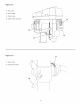
Figure 2-1 11 1, BeHtcover 2, BeHttension handHe 3, Motor 4, QuHHHock 5, Feed handHes 6, Keyed chuck 7, CoHumn 8, TaMe 9, TaMe raise/Hower HandHe 1O, Base 11, ON/OFF switch 12, FHexibHeHamp 9
Figure 2-2 13, ON button 14, OFF paddHe 15, Depth scaHe 16, Depth scaHequick Hock 16 14 15 Figure 2-3 17 17, BeveH scaHe 18, TaMe HockhandHe 18 10
UNPACKUNG AND CHECKUNG CONTENTS Compare the items to figures below; verify that all items are accounted for before discarding the shipping box, if there are any missing parts, call Customer Helpline 1 °800°897°7709, This drHUpress wHUrequire some amount of assemMy, Remove aH of the parts from the shipping box and Uay them on a clean work surface, Remove any protective materiab and coatings from aH of the parts and the drHUpress, The protective coatings can be removed by spraying WD°40 on them and wiping
Figure 3-2 L H G m J Q K N P F_ M Y X S R T U Q, 5mm Hex wrench Feed handHe (3) G, Chuck arbor R, SpindHe adapter remover H, Keyed chuck S, Hex head screw M8-1,25 x 125mm (4) H, Chuck key T, FHatWasher M8 (8) J, Worm gear U, Lock Washer M8 (4) K, Knob V, Hex Nut M8-1,25 (4) L, TaMe raise/Hower handHe W, Adhesive cord champ (2) (not shown) M, TaMe HockhandHe X, Cord sHeeve N, Y, Cord champ O, 3mm Hex wrench Z, Lock washers (2) R AA, Hex socket head screw M6
TOOLS REQUIRED Figure 4-2 The following toob are needed for assemMy and alignment, Note: Hex wrenches are provided, The remaining toob are typbaU shop tooUsand are not included with your ddH press, 12mm Open end wrench #2 PhHHpsscrewdriver 13mm Open end wrench Hammer and Mock of wood * The drHUpress is a heavy machine; two peopb may be required for certain assemMy operations, * DO NOT assembb the ddH press until you are sure the tooUis unpUugged, * DO NOT assembb the ddH press until you are sure the p
Figure 4-4 Figure 4-6 L O P N The drill press is a heavy machine; two people may be required for certain assembly operations, 5, Slide the rack (F) and the table (L) onto the column (A), See Figure 4-4, Figure 7, Attach the knob (N) to the table raising and lowering handle (O), See Figure 4-6, 8, Attach the table raising and lowering handle on the worm gear shaft (I) and tighten the set screw (P) against the fiat (R) on the worm gear shaft, 4-5 Figure 4-7 S 6, Place the ring (E) onto the
DRILL PRESS HEAD AND MOTOR ASSEMBLY Figure 5-3 The ddH press is a heavy machine; two peopb may be required for certain assemMy operations, E MAKE CERTAIN the ddH press is disconnected from the power source, Figure 5-1 F A E 3, Thread the three feed handles (E) in the three tapped hobs located in the pinion shaft (F), 1, Seat the ddH press head (A) on the coUumn (B), See Figure 5-1, Figure Figure 5-4 5-2 IG C 2, NOTE: Make certain that the chuck arbor taper (G) and the tapered hob in the
Figure FASTENING 5-5 Figure 5, DRILL PRESS 5-6 Scat the chuck onto the drHUpress spindb as far as it wHUgo, Carefully drive the chuck onto the spindb by pUacing a wooden Mock (K) under the chuck (L) and tap the Mock up with a hammer (M), IMPORTANT: DO NOT tap the chuck directly with a mctaU hammer, A To help reduce the tendency of the drill press to tip over, slide, or walk, it can be fastened to the floor surface, The machine base has four hobs (A), one at each corner where it can be fastened (h
Figure 7-2 ,, DO NOT expose the drHHpress to rain or operate the in damp Hocations. ,, MAKE SURE aHHparts have been assembHed correctly and are in working order. SWITCH OPERATION CHILDPROOF THE WORKSHOP AREA by removing switch keys, unpHugging tooHsfrom the eHectricaHreceptacHes, and using padHocks. Figure 7-1 p- ............... \ 6. To use the Drill Press, unlock and remove the padlock from the "ON" button.
TABLE OPERATION Figure 9-I Figure 9-3 B F 5, 1. To raise or bwer the tame (A) on the coUumn (B), bosen the tame bck handb (C). See Figure 9-1. Figure 6, The tame can be tilted right or bft by bosening the tame bcMng bout (E), then removing the tame alignment pin (F). See Figure 9-3. The table can now be tilted to the desired angle. The table locking bolt then must be tightened. 9-2 Figure 9-4 G 200 100 0 10° 200 300 H 2.
DRULL SPEEDS MAKE CERTAIN the drill press is disconnected from the power source, Nine drill speeds (150, 275, 325, 460,500,540, 1150, 1550 and 2200 RPM) are available with your drill press, See Figure 10-1 to select the correct spindle speed for your operation, This diagram can also be found on the inside of the belt cover of the drill press, Figure 10-1 Recommended Dri|| Press Size JSoftwo0d J Hardw0odJ Acryib J Twist }]rill }]its !/0" - 3/10" 2200 2200 2200 1/4" - 3/8" 2200 1550 2200 7/16" - 5/0" 1
DRULLING HOLES TO DEPTH ADJUSTING SPRUNG The drHUchuck wHUautomatically return sUowUyto its upper position when the handUe is reUeased, The return spring was properUy adjusted at the factory, However, to adjust, if necessary: MAKE CERTAIN the drill press is disconnected from the power source. Figure RETURN 12-1 MAKE CERTAIN the drHUpress is disconnected from the power source. Figure 13-1 A 1. 1. 2. Unsert the drHUbit into the chuck and tighten with chuck key. Loosen both nuts (A) and (B).
iNSTALLiNG AND REMOVING DRULL BIT NEVER run drill press to install or tighten a drill bit or cutter in the chuck. MAKE CERTAIN the drill press is disconnected from the power source. Figure 14-1 SUPPORTING WORKPIECE USE only recommended Figure accessories. 15-1 B o \ 1, Hold the chuck barrel (A) and turn the top collar (B) clockwise to dose the chuck jaws (C), See figure 14-1. 2. Open the chuck jaws slightly larger than the diameter of the drill bit 3.
QUILL in wood, These bits cut a fiat bottom hob and are LOCK designed for removal of wood chips, Do not use hand bits which have a screw tip or auger bits, At drill press speeds, they will lift and rotate the workpiece, The quill allows the up and down movement of the chuck, Different setup or working operation may require the quill to be lower and locked into position, Figure 18-1 For through boring, align the table so that the bit will go through the center hob, Scribe a vertical line on the front
CHANGmNG MOTOR VOLTAGE MAKE CERTAIN to disconnected the machine from the power source before working on motor. Turn the power switch OFF and unplug the power cord from its power source, Have a certified eUectrbian make aft eUectrbaUconnections. Aft UocaU and state codes must be maintained. The motor supplied with the DrHUPress is a duaUvoUtage 120/240°voUt, singb phase motor. The motor is wired from the factory for 120°voUtoperation.
TOPREVENT INJURYTOYOURSELF or damageto thedrHU press,turntheswitchtotheOFFpositionandunpUug thepowercordfromtheeUectricaU receptacle beforemakinganyadjustments, PROBLEM UKELY CAUSE(S) SOLUTION Motor does not start or does not come up to full speed 1. Switch key is removed 1. insert switch key. 2. Defective switch 2. Have switch replaced. 3. Defective capacitor 3. Have capacitor replaced. 4. Low line voltage 4.
204n.BenchDrill Press MODELN0.152.229020 Whenservicing,useonlyCRAFTSMAN replacement parts,Useof anyotherpartsmaycreatea HAZARD or cause productdamage, Anyattemptto repairor replaceelectricalpartsonthisdrillpressmaycreatea HAZARDunlessa qualifiedservice technician doesrepairs,Repairserviceis availableatyournearestSearsServiceCenter, Alwaysorderby PARTNUMBER, not by key number, KEY NO. PART NO. DESCRiPTiON QTY. KEY NO. PART NO. DESCRiPTiON QTY.
20-in.BenchDrill Press KEY NO= PART NO= DESCRIPTION 97 0R92366 Indicator 98 0R92484 Rack 99 0R92485 100 MODELN0.152.229020 KEY NO. PART NO. DESCRPTUON 1 123 QR92450 Motor Cord 1 1 124 QR93456 Wiring Diagram 110/220V, Forward/Reverse 1 Base 1 125 QR93454 1 0R92725 M8x125mm Hex Hd Screw 4 126 QR93538 Motor Specification Label M8x12mm Hex Soc Set Screw 101 0R9!499 M8.4 Flat Washer 8 127 QR92443 Motor Pulley 1 102 0R90248 M8.
20-in.BenchDrill Press MODELN0.152.229020 1.
1 Cabalio de Fuerza (servicio continuo) 2 Cabamios de Fuerza (m_×imo desarrotiado) 9 Velocidades, Polea Escatonada Gama de Venocidades de PerforaciOn 150°2200 R.P.M Modelo No. 152.229020 L_ C PARA SU SEGURJDAD PERSONAL, Reay obedezca todas Uas lnstrucciones de Seguddad y Operaci6n antes de operar esta Taladradora de Banco Linea de Ayuda al Qiente 1-800-897-7709 Sirvase tenor listo su No. de Modelo y No. de Sede Sears, Roebuck and Co. Hoffman Estates, JL (}0179 U.S.A. No.
SECO[ON PAG[NA Garant_a .............................................................................................................................................................. 30 Especificacionesde[ producto................................................................................................................................ 31 [nstruccionesde seguridad....................................................................................................................................
Ta[adradora _ecificaciones de Banco de 20 pu[g° deI Motor: Operaci6n de agarradera Rotaci6n a 360 grados Control del motor Pulsador tipo industrial de ENCENDIDO / APAGADO Tipo de motor Inducci6n Servicio continuo 1 HP Maximo desarrollado 2 HP Amperios 12/6 Inclinaci6n de mesa S[ Voltios 120/240 Movimiento CremalIera y piff6n Fase Monofasico Material de mesa Hierro moldeado Hertzios 60 Tope de profundidad Sf R.RM.
INSTRUCCIONES DE SEGURIDAD GENERALES El uso de una taIadradora puede ser peligroso si se hace caso cruise de la seguridad y el sentido comon. El operario debe estar famifiarizado con et funcionamiento de esta herramienta. Lea este manual para entender esta taladradora. NO OPERE esta taladradora si no entiende plenamente las Iimitaciones de esta herramienta. NO MODIFIQUE este taIadradora de ninguna manera. REOUERDE: Su seguridad personal es su responsabiiidad. 2. UTILICE PROTECCION OCULAR SlEMPRE.
21. NUNCA DEJEUNAM_,QU_NA ENFUNCJONAM_ENTODIRECTRJCES PARA LAS SiNATENDER Apague elinterrupter deenerg[a a Ia EXTENSUONES ELECTRICAS posici6n de"OFF" (apagado). NOsealejedeJamb, quina Mientras menor sea el n0mero de calibre, mayor sera el hastaquesehayadetenido percompbto. diametro de la extensi6n electrica. Si tiene dudas sobre las 22.
REPONGA _NMEDJATAMENTE CUALQUJER CORDON DANADO O GASTADOo ESTA HERRAM_ENTA DEBE ESTAR CONECTADA A TIERRA DURANTE EL USO PARA PROTEGER AL OPERAR_O CONTRA LOS CHOQUES ELECTR_COS.
Tambien ser_. necesario reemplazar el enchufe de 120 voltios suministrado con el motor con un enchufe aprobado pot UL/CSA y apto para el funcionamiento a 240 voltios y la corriente tasada de la taladradora. Comunfquese con un electricista local competente para los procedimientos correctos para instalar e! enchufe. La taladradora debe cumplir con todos los c6digos locales y nacionales despues de la instalaci6n del enchufe de 240 vottios.
19.REPONGA cualquier cord6ndaBado inmediatamente. NOutiliceuncord6n o enchufe daRado. SiIataladradora nofunciona correctamente, o sisehadaRado, deiado a Haintemperie o entrado encontacto conagua,devueJvala a uncentredeservicio Sears. 20. AFJANCE lataladradora alsuelooa unbancodetrabajo.Lasvibraciones pueden hacerquelamaquina se deslice, camine o sevuelque. 21. AFIANCE el material firmemente contralamesa.
Figura 2-1 11 1, Cubierta de la correa 2, Agarradera de tensi6n de correa 3, Motor 4, Cierre del arbol hueco 5, Agarraderas de alimentaci6n 6, Mandrino con Ilave 7, Columna 8, Mesa 9, Agarradera de izado / bajada de mesa 9 10, Base 11, hterruptor de ENCENDDO / APAGADO 12, Lampara flexible 37
Figura 2-2 13. Bot6n de ENCENDDO 14. Paleta deAPAGADO 15. Escala de profundidad 16. Cierre rapido de la escala de profundidad 16 14 15 Figura 2-3 17 17. Escala de biselado 18.
DESEMPAQUE Y COTEJO DEL CONTENIDO Asegurese de frotar la cera para eliminada antes dei montaje. Compare los art[culos con la Figura 3-1 abajo y compruebe que todos los art[culos esten contabilizados antes de descartar Ia caja de envio. Si faltan piezas, comun[quese con la L[nea de Ayuda al Cliente aI 1-800-897-7709. Esta taladradora necesitara cierta cantidad de montaje. Quite todas Ias piezas de la caja de env[o y col6queias sobre una superficie de trabajo limpia.
Figura 3-2 L H G I K J Q N P R M Y X S R Agarradera de alimentaci6n G. T (3) U R. Desmontador del adaptador del huso _,rboI deI mandrino S. Tornillo de cabeza hexagonal M8-1.25 x 125 mm (4) H. Manddno con Ilave T. Arandela plana M8 (8) I. Llave deI mandrino U. Arandela de cierre M8 (4) J. Engranaje helicoidal V. Tuerca hexagonal K. Perilla W. h Agarradera de izado / bajada de la mesa Abrazaderas ilustradas) M. Agarradera de cierre de Ia mesa X.
HERRAMIENTAS REQUEF_IDAS Figura 4-2 Se requieren Ias siguientes herramientas para el montaje y alineaci6n. Aviso: Se proporcionan las !laves hexagonales. Las herramientas restantes son herramientas t[picas de taller que no estan incluidas con su taladradora. Llave de boca de 12 mm Destornillador Phillips #2 Llave de boca de 13 mm Martillo y bloque de madera * La taladradora es una mAquina pesada. Podr_n requerirse dos personas para ciertas operaciones de montaje.
Figura 4-4 Figura 4-6 L 0 P N La taIadradora es una mb,quina pesada. Podr_.n requerirse dos personas para ciertas operaciones de montaje. 5. Deslice la cremalIera (F) y la mesa (L) sobre la columna (A). Ver la Figura 4-4. Figura 7. Conecte la perilla (N) a la agarradera de izado y bajada de mesa (0). Vet Ia Figura 4-6. 8.
MONTAJE DEL CABEZAL Y EL MOTOR DE LA TALADRADORA Figura 5-3 o La taladradora es una maquina pesada. Podran requerirse dos personas para ciertas operac[ones de montaje. o ASEGORESE de que Ia taladradora la fuente de suministro. Figura este desenchufada de 5-1 A 3. 1. Asiente el cabezal de la taladradora (B). Ver la F[gura 5-1. Figura Enrosque Ias tres agarraderas de alimentaci6n (E) en los tres agujeros roscados IocaIizados en el eje del piB6n (F).
Figura AFIANZANDO 5-5 Figura 5. Asiente el manddno sobre eI huso de Ia tatadradora LA TALADRADORA 5-6 Io m_ximo posible, co!ocando un bloque de madera (K) debajo del mandrino (L) y golpeando el bloque con cuidado hacia arfiba con un martillo (M). tMPORTANTE: NO golpee el mandrino directamente martillo de metal. con un A Para ayudar a reducir Ia tendencia de Ia taladradora a volcarse, deslizarse o "caminar", se le puede afianzar a la superficie de! suelo.
Figura 7-2 / NO exponga Ia ta[adradora a la Iluvia n[ tampoco la opere en lugares h0medos. /c o ASEGURESE de que todas ias piezas hayan side correctamente montadas y esten en funcionamiento. OPERACION / DEL CONMUTADOR i HAGA SU TALLER A PRUEBA DE NIItOS quitando las Ilaves de los interruptores, desenchufando Ias herramientas de los tomacorrientes y haciendo use de candados. Figura 7-1 p- ............... \ IX..................... 6.
OPERACI6N Figura DE LA MESA Figura 9-3 9-1 B F La mesa puede inclinarse a Ia derecha o izquierda afiojando el perno de cierre de la mesa (E) y Luego quitando el pasador de alineaci6n de mesa (F). Ver la Figura 9-3. Para elevar o bajar la mesa (A) en Ia columna (B), afioje la agarradera de cierre de la mesa (C). Vet la figura 9-1. Figura 6. La mesa podra indinarse ahora al anguIo deseado. El perno de cierre de la mesa debe apretarse entonces. 9-2 Figura 9-4 G 200 100 0 10° 200 300 H 2. 3.
VELOCIDADES ASEGURESE DE LA TALADRADORA de que la taladradora este desconectada de Ia fuente de energ[a. Hay nueve velocidades de taEadrado (150, 275, 325, 460, 500, 540, 1150, 1550 y 2200 RPM) disponibles con su taladradora. Ver la Figura 10-1 para seIeccionar la velocidad de huso correcta para su operaci6n. Este diagrama tambien podra hallarse dentro de la cubierta de la correa de la tatadradora.
PERFORANDO AGUJEROS A PROFUNDIZ)AZ) ASEGURESE de que la taladradora fuente de energ[a. Figura AJUSTANDO este desconectada EL RESORTE DE RETORNO El mandrino de la taladradora regresara lentamente y de forma automatica a su posici6n superior al soItar Ia agarradera. El resorte de retorno fue ajustado correctamente en Ia fabrica. Sin embargo, si resulta necesario efectuar ajustes: de Ja 12-1 ASEGORESE de que Jataladradora la fuente de energ[a. Figura este desconectada de 13-1 A 1. 1.
INSTALACION Y DESMONTAJE DE LA BROCA JAMAS haga uso de la taladradora para instatar o apretar una broca o cortador en el mandrino. ASEGURESE de que la taladradora fuente de energ[a. Figura este desconectada de Ja APOYANDO EL MATERIAL 14-1 SOLO utiiice accesorios recomendados. Figura i %" I 15-1 A -"_C B o \ 1. Sujete eI barriI dei mandrino (A) y gire el collar[n superior (B) en sentido horario para cerrar Jas mand[bulas del mandrino (C). Vet Ja Figura 14-1. 2.
ENCLAVAMIENTO DEL ARBOL HUECO astiIlas de madera. No utilice las brocas de mane con punta de torn[llo, ya que a Ias velocidades de la taIadradora, levantaran y haran girar la madera. El _.rbol hueco permite el movimiento de! mandrino hacia arriba y abajo. Las configuraciones de montaje o las operac[ones de trabajo distintas podran exigir que el arbol hueco este m#ts bajo y enclavado en su sitio.
CAMBIO DEL VOLTAJE DEL MOTOR LUBRICACK_N ASEGURESE de desconectar la maquina de Ia fuente de alimentaci6n antes de trabajar en el motor. APAGUE el interruptor y desenchufe la fuente de suministro= P[dale a un electricista certificado que haga todas Ias conexiones electricas. Se deben mantener todos los c6digos locales y estatales. EI motor que se suministra con Ia Taladradora es un motor monofasico de doble voltaje para 120/240 V. E! motor esta alambrado de fabrica para funcionar con 120 V.
PARA EVSTAR HERIRSE A Si rWlSMO o causar daf_o a la taladradora, conmute el interruptor a la posici6n de apagado (OFF) y desenchufe el cord6n de energ[a del tomacorrientes antes de realizar cuaIquier ajuste= PROBLEMA Motor 130 arranca O nO aIcal3za velocidad plena CAUSA(S} POSIBLES SOLUCJ6N 1. Llave de! interruptor fuera de su sitio 1. Inserte la Ilave del interruptor. 2. Interruptor defectuoso 2. Mande a reponer e! interruptor. 3. Capacitador defectuoso 3. Mande a reponer el capacitador. 4.
Taladradora de Banco de 20 Pulg, NO. DE MODELO Cuando vaya a rendir servicio, s61o utilice piezas de recamb[o CRAFTSMAN. un PELJGRO o producir dahe al producto. 152,229020 El use de cualquier otro tipo de piezas podrb, crear CuaIquier intento per reparar o reemptazar Ias piezas electricas de esta taladradora podrb, crear un PELIGRO a menos que la reparaci6n sea efectuada por un tecnico de servicio competente. El servicio de reparaci6n esta disponible en su Centre de Servicio Sears mas cercano.
Tatadradora de Banco de 20 Pumg, No de No. de Clave Piezas Descripci6n 97 OR92366 Indicador 98 OR92484 99 NO. DE MODELO 152,229020 No de No. de Clave Piezas Descripci6n 1 123 0R92450 Cord6n del motor Cremall÷ra 1 124 0R93456 Diagrama OR92485 Base 1 125 0R93454 Etiqueta espec, motor 1 100 OR92725 Tornillo de cab, hex M8 x 125 mm 4 126 0R93538 Tornillo de fijaci6n cab, hueca hex, M8 x 12 mm 1 101 OR91499 Arandela plana M8.
Tatadradora de Banco de 20 Pumg, NO, DE MODELO (2} 95 g4 105 55 152,229020
iiiiiiiiiiiiiiiiiiiiiiii!_ ...... You r Ho m e For repair-in your home-of all major brand appliances, lawn and garden equipment, or heating and cooling systems, no matter who made it, no matter who sold it! For,the replacement parts, accessories and owner s manuals that you need to do-it-yourself. For Sears professional installation of home appliances and items like garage door openers and water heaters. 1-800-4-MY-HOME Call anytime, ® (1-800-469-4663) day or night (U.S.A. and Canada) www.sears.