
Operating instructions
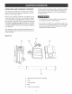
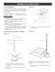
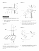
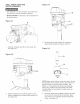
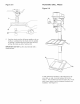
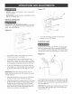
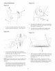
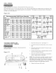
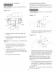

TABLE OPERATION
Figure 9-I
B
Figure 9-3
1. To raise or bwer the tame (A) on the coUumn (B),
bosen the tame bck handb (C). See Figure 9-1.
Figure 9-2
F
5,
6,
The tame can be tilted right or bft by bosening the
tame bcMng bout (E), then removing the tame align-
ment pin (F). See Figure 9-3.
The table can now be tilted to the desired angle.
The table locking bolt then must be tightened.
Figure 9-4
G
200 100 0 10° 200 300
2. Turn the tame raising and [owering handUe (D)
c[ockwise to raise the tame and counter-cUockwise
to [ower the tame. See Figure 10-2.
3, After the tame is at the desired height, tighten the
tame bck damp.
NOTE: AUways raise (rather than bwer) the tame to the
finaUposition to allow the gears to mesh and prevent
slippage.
4,
The table (A) can be rotated 360 degrees on the
column (B) by loosening the table lock clamp (C)
and rotating the table to the desired position, and
tightening the table clamp. See Figure 9-1.
H
7,
8,
A tilt scale (G) is provided on the table bracket cast°
ing to indicate the degree of tilt. A witness line (H) is
provided on the table to align with the tilt scale.
See Figure 9-4.
NOTE: When the table is returned to the level
position, replace the table alignment pin, This wiii
position the table surface 90 degrees to the spindle,
The table locking bolt then must be tightened,
18