
Operating instructions
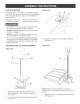
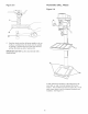

DRULL SPEEDS
MAKE CERTAIN the drill press is disconnected from the power source,
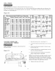
Nine drill speeds (150, 275, 325, 460,500,540, 1150, 1550 and 2200 RPM) are available with your drill press, See
Figure 10-1 to select the correct spindle speed for your operation, This diagram can also be found on the inside of
the belt cover of the drill press,
Figure 10-1
Recommended Dri|| Press Speeds
Size JSoftwo0d JHardw0odJ AcryibJ Brass _ Steel
Twist}]rill }]its
!/0" - 3/10"
1/4" - 3/8"
7/16" - 5/0"
11116"- t"
BradPointBits
!/8" - 1/4"
310"
1/2"
5/8"
3/4"
1 _
Forstner8its
I/4" " 3/8"
I12" - 510"
3/4"- 1"
I-I18" - 1-114"
1-310"- 2"
2200 2200 2200 2200 2200 12200
2200 1550 2200 tt50 2200 11t50
1550 570 1550 570 1550 570
570 540 NR 325 570 325
1550
1550
1550
1550
1!50
1150
1150 1550 NR NR NR
570 1550 NR NR NR
570 1150 NR NR F==_
540 570 NR NR NR
275 570 NR NR NR
275 275 NR NR NR
2200
2200
1550
1t50
540
570 NR NR NR NR
540 275 NR NR NR
540 275 NR NR NR
275 275 NR NR NR
275 NR NR NR NR
NR = NOT RECOMMENDED
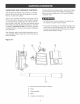
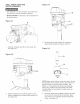
SPINDLE MOTOR
PULLEY PULLEY
2200
1t50
EGG
SPINDLE MOTOR
PULLEY PULLEY
MOTOR PULLEY
15G
t 550
540
460
2'75
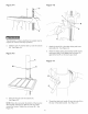
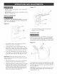
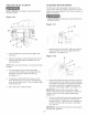
CHANGING SPEEDS AND
ADJUSTING BELT TENSION
MAKE CERTAIN the drill press is disconnected from
the power source,
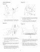
Figure 11-1
E
A
C B
E
D
1, Open the belt cover (A), See Figure 11=1,
2, Loosen the tension lock knobs (B), one is on each
side,
3, Rotate the belt tension handle (C) forward, away
from the motor (D),
4, Position both belts (E) on selected pulleys accord-
ing to the drill speed diagram,
5, Rotate the belt tension handle back, towards the
motor to apply tension on the belts,
NOTE: The belt should be just tight enough to prevent
slipping, Excessive tension will reduce the life of the
belt, pulleys and bearings, Correct tension is obtained
when the belt can be flexed about 1" out of line midway
between the pulleys using light finger pressure,
6, Tighten both tension lock knobs,
19