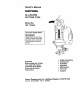
Owner's Manual CRRFTSHRN® ALL-IN-ONE CUTTING TOOL Model No. 183.172540 Important Safety Notice [_, WARNING I Always have one hand firmly placed on the tool body while operating, Never operate the tool by holding only the tool handle. • Safety Instructions CAUTION: • Accessories Before using this Cutting Tool, read this manual and follow all its Safety • Assembly • • Operation Maintenance Rules and Operating Instructions, • Parts • Espanol Sears, Roebuck and Co.
Safety and Assembly Instructions ASSEMBLY CRRFTSMRN® FLEX SHAFT for ALL-IN-ONE CUTTING TOOL Model No. 183.287660 INSTRUCTIONS t. Turn cutting tool motor switch OFF and remove plug from the power source. 2. Lock main shaft (3) by rotating the collet nut (1) while pressing on the spindle lock button (4) until the spindle lock prevents shaft from rotating (see Fig 1). 3. Use cutting tool fiat wrench (5) to loosenthe collet nut by turning it counter clockwise.
SECTION Warranty ........................................ ProductSpecifications...................... PowerTool Safety ............................ CuttingToct & AccessorySafety ......... ElectricalRequirement& Safety .......... CuttingTootSymbols........................ PAGE 2 2 3 4 5 6 SECTION ACCSS_ PAGE .................................... Carton Contents .............................. Know Your Cutting Toct .................... Assembly & Operation ...................... Maintenance ...............
Safety and Assembly ASSEMBLY 6. 7. INSTRUCTIONS Instructions - cont'd Align the flex shaft connector cap (6) wfth the cutting tool motor housing (8) (see Fig. 3). NOTES: a) Carefully align the square end of the flex shaft center core so it will engage into the square hole in the collet. b) Make sure the keyway (7) in the inside of the connector cap aligns with the matching key (8) on the motor housing. c) Oocasionally the flex shaft inner core may slide out of the outer casing durthg handling.
[_ WARNING--] Before using your cutting tool, it is critical that you read and understand these safety rules. Failure to follow these rules could result in serious injury to you or damage to the cutting tool Good safety practices are a combination of common sense, staying alert and understanding how to use your power tool.
SERVICE ANGLE GRINDER SAFETY L='wAr.J.G I Tool service must be performed only by qualified personnel Service or maintenance performed by unqualified personnel could result in risk of injury. Always wear safety goggles with side shields or a face mask when using the angle grinder attachment. High speed grinding and sanding will throw hot sparks and dust particles that could cause serious injury to your eyes. When servicing a tool, use only identical replacement parts.
IZolUl;pie;il_ F;ll I IP'_,IIIfe__ This cutting tool is double insulated to protect you from el_l shock, WARNIN N Double Insulated tools are equipped with a polarized plug (one blade is wider than the other). This plug will fit Into a polarized outlet only one way. If the plug does not fit fully into the outlet, reverse the plug, If it still does not fit, contact a qualified electrician to install a polarized outleL Do not alter the plug In any way.
IA WARNING I Some of the following symbols may be your tool. Please study them and learn meaning. Proper interpretation of these will allow you to operate the tool better used on their symbols and safer. ® This symbol designates that this tool is listed with U.S. requirements by Underwriters Laboratories.
AVAILABLE ACCESSORIES CUTTING IA WARNING J KEY Use only accessories recommended for this cutting tool. Follow instructions that accompany accessories. Use of improper accessortes may cause injury to the operator or damage to the Cutting Tool.
M K_ D H G 8 F;
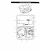
Loop precision Handle Motor Housir H_ng C:) < Quick Lod_ng Le_r Adjusting KnOb I_ver ,So4e Prate Motor Housir Motor Housing Depth StopRod DepUl SCale Height Mounting Knobs Quick Lever PSunge Action Turret Rip Knob Sole Adjusting Pla_eLoc_ Knob Mounting OLSC Base Rip Fence Mount
Grinding Handle Mounting Colla¢ Lockln Button Cc41et Nut Qulc_ Connect Lever Connector Cap lO
INSTALLING CU'FrlNG BITS - Cont'd I_ WARNINGI Remove the plug from the power assembly, changing accessories making adjustments. This safety prevent accidental starting of the result in serious injury. ON / OFF & SPEED CONTROL source before or cutters and action will help tool which could 4. insert new cutting bit (4) into the coliet. IA w a=aGI Insert the bit all the way into the coget and then pull it back between _/16" and 1/=,,.
CHANGING COLLET INSERT INSTALLING The cuffing bits for this toot are locked into place with a collet nut (t) and coflet (see Fig. 3). The l/a" collet (2) is used for holding hobby tool accessory bits. The ¼" collet (3) is supplied for holding SMALL router bits with a ¼" shank. FREEHAND CU'I-rlNG GUIDE - cont'd 1.
PRACTICE CUTS USING FREEHAND GUIDEcontfd CU'I"TING [,_ WARNtNG ) Have you read "POWER TOOL SAFETY", "CU'I_ING TOOL SAFETY", "ELECTRICAL REQUIREMENTS & SAFETY" AND "CUTTING TOOL SYMBOLS" on pages 3, 4, 5 and 6 or'this manual? if not, please do it now before you operate this Cutting Tool Your safety depends on iti Every time you use the Cutting Tool you should verify the following: 1. Cutting Tool cord is not damaged. 2. Bit is correct type for the material being cut. 3.
CUTTING OUTLET OPENINGS IN DRYWALL cUTrlNG IA DANGERI Do not attempt to use this tool to make cut-outs around any fixture or opening which has live electrical wires or on any wail which may have electrical wiring behind it. If a live wire Is contacted, the bit could conduct the electric current to the tool, creating an electrocution hazard for the operator. Turn OFf: breakers or remove fuses to disconnect the electric circuit in the area of work.
ADUSTING [4_lvJ[s%vl_,_ .=tnl:::li _,f.'l_II] _ FREEHAND CuI-rlNG GUIDE-Cont'd INSTALLING REMOVABLE HANDLE The removable handle is designed for use when precision control over the tool movement is desired. The comfortable handle can be used with either the right or left hand. Fig. 14 Slide removable handle mounting bracket (1) onto the bottom of motor housing (2) until the slot under the handle (3) lines up with the shaft locking button (4) in the motor housing (see Fig. 10).
_HI:._]m::l'_o41JW|l_[_[eLWlle] CIRCLE CUTTING CIRCLE CUTTING GUIDE OPERATFON ),A WARNING I Unplug the tool from tt3epower source before changing accessories, changing bits and making adjustments. 5. Turn the switch ON. 6. When the motor is up to full speed, slowly tip the tool and circle cutting guide assembly to an Upright position, letting the bit cut nte the workpiece (see Fig f4J. Be careful to keep the p vo point ocated at the centre of the circle to be cut.
I "Jllll+[_ SETTING ROUTER DEPTH FOR SINGLE DEPTH ONLY :11:ts]lJl I1: =i :r_*!:j The router accessory Converts your Cutting Tool into a small hobby plunge router that is capable of handling small _" shank router bits as well as the spiral cutting bit. The tilting base is ideal for bevel cutting. The plunge feature allows you to pre-set up to three different cutting depths. Depth of cutting is controlled by sliding the muter base up and down on the guido rods and locking it in place. 1.
SEI-FING PLUNGE DEPTH - cont'd SET'rING 4, Loosen both height adjusting knobs (6) by turning them counter-clockwise. Bevel cutting with the cutting bit can be done with the router base tilted to the desired angle. NOTE: Only loosen height adjusting knobs enough to release the tension on the guide rods (7). 1. Loosen both bevel adjusting locks (1) by pulling them outward from the router base (2) (see Fig. 18). Slide router base (8) up or down to obtain the desired depth of cut. 2.
I I FREEHAND ,] I[ I I _ [€l :il _._[aJlj I q _1 :]r:_,.'l CUTI'ING I AND ROUTING CuI-rlNG STRAIGHT UNE WITH STRAIGHT EDGE When the router base accessory is installed on the Cutting Tool, it will function as a small router to be used for freehand cutting of irregular shaped patterns. You can cut patterns out of the workpiece with the cutting bit or route patterns into the workpiece with small muter bits. To cut a straight line. you can use a straight edge template to guide the muter base. 1.
_1nn. Jl_[e_=8:_oll InII::l_..8:__,_! CU'I-rlNG CURVED LINE WITH A TEMPLATE INSTALLING To cut a curved line, you can use a curved template to guide the router base. 1. Make a template from hardboard or other similar material to the shape you require (see Fig. 21). NOTE: Radius of curve must be greater: than 2½" for router base to propedy follow the curved template. RIP FENCE TO ROUTER BASE 1. Loosen all three cap screws (1) in the router base using a 7 mm wrench (see Fig. 22).
2, Match up key (2} on motor housing and slot (3) in angle grinder attachment. There are also arrows on the motor housing and angle grinder attachment housing. Slide angle grinder attachment onto the motor housing. NOTE: While sliding angle grinder attachment onto motor housing, rotate the angle grinder attachment spindle (4) until flex shaft adaptor engages into the angle grinder attachment.
INSTALLING GRINDING DISC - cont'd SAFETY EQUIPMENT ATrACHMENT I_ 5 WARNING FOR ANGLE GRINDER I Your angle grinder attachment is a high speed tool that will throw hot sparks and metal dust when grinding. It will also throw particles and dust when sanding, it is critical that you use proper safety goggles, dust mask and hearing protection at all times while operating this tool. -- 7 PLACEMENT OF GUARD Fig. 26 INSTALLING 1. 2. 3.
Ig=F.'4J:lg; _._]"r:_;i ALWAYS WEAR EYE PROTECTION. 4. Insert collet with square hole (5) into main shaft (3) and re-install the collet nut onto the main shaft (see Fig. 30). NOTE: Collet with square hole is packed in Polybag #2. 5. Use Cuthng Tool wrench to tighten the collet nut firmly onto the main shaft while spindle lock is engaged into the main shaft. Any power tool eyes which could cause permanent eye damage.
For your own safety, turn the switch OFF and remove the plug from the power source before maintaining your Cutting Tool. When servicing, use only identical parts. Use of any other part may create a hazard or cause product damage. EXTERNAL CLEANING __. WARNING J DO NOT use solvents when cleaning plastic parts. Most plastics are susceptible to damage from various types of commercial solvents and may be damaged by their use. Use clean cloth to remove dirt, dust, oil, grease, etc.
Main Unit 77 84 41 25
IA WARNINGI When servicing use only CRAFTSMAN® cause damage to your Spin Saw. replacement Any attempt to repair or replace electrical performed by a qualified technician. parts. Use of any other parts may create a HAZARD or parts on this Cutting Tool may create a hazard unless repair is Always order by PART NUMBER, not by key number. Main Unit Key# 1 2 3 5 10 11 12 Part # 01AR-000032-00 01AR-O00035-00 01AT-O00OI4-A0 01AT-000031-00 02.
Freehand Cutting Guide Assembly 211 214 203 216 213 Key # 201 202 203 208 211 212 213 214 215 216 Part # 02.AF-000041-10 02AF-000076-00 22t8-MA0001-00 2218-MA0001-01 02.
Handle Assembly 328 329 3O5 306 331 _330 / 301 326 3O7 312 3O2 Key # 301 302 Part # 02AF-000041-10 02AF-000076-00 2218-MA0001 `00 2218-MA0001-01 306 307 308 310 Key # 312 1 324 1 Part # 2213-MA0013-00 2213-PA0010-00 2213-PA3O10-01 Part Name S-round guide holder Lock Lock 2213-PA0012`00 Plastic guide base 1 2213-PA0013-00 Adjustment Gear 15T 1 325 2213-PA0014`00 Sleeve 1 1 326 2213-PA0015-00 Screw lock F 1 2 2 1 327 2213-PA0016-00 22t3-PA0017`00 2213-PA0017-01 Anx dght
Circle Cutting Guide Assembly (_ .21 4 20 11 -10 12 7 3 Q. 2 19 Key # 2 3 4 6 7 10 11 12 16 17 18 19 20 2t part # 02AN-000018-00 02AN_00018-10 02AN-000028-Q0 02AS-000258-00 02AS-000258-10 02.AS-0O03t 9_0 02AW-000022-B0 2206-MA0001-00 2206-MA0005--00 2206-MA0002-00 2206.-MA0003-00 2206.
Router Assembly 157 120 109 133 139 _66 119 t 39 0 155 102 13 102 101 3(
Router Key # 101 Part # 02AF-000041-10 102 103 104 02AF-000077-00 02AF-000078-00 02AG-000145-00 105 02AJ-000017-00 107 02AH-000107.
Flex Shaft Assembly 37 5 13 4 14 34 3 1 24 In 32
Flex Shaft Assembly Key # 1 Part # 01AT-000034-00 2 01AT-000038-00 01AT-000039_0 02AE_00045-30 02.AH-000073-10 4 8 9 1(3 11 2220-MA0002-00 02.
Angle Grinder Assembly O o Angle Grinder Handle Assembly 2 34
Angle Grinder Assembly Key # t 2 3 4 5 Part # 02AE-000037-OO 02AE-000049-00 02AE-000067-00 02AF-000041-10 02AF-000025-10 Part Name Scaring Bearing Scaring Fixing shaft Anvil lock pin Qty 1 1 2 1 1 Key # 32 33 37 38 Part # 02AH-000127-00 2221-MA0006-00 2221-MAO009-00 2213-PA0005-01 2221-PA0001-00 6 02AF-000083-00 2221-MA0010-O0 Release lock pin Release lock pin 1 1 39 40 2221-PA0002-00 2221-PA0003-00 9 02AG-000153-00 23T Gear 1 10 02AG-000154-00 14T Gear 11 02AH-000120-00 14 Part Nam