Operator’s Manual ® THREE BIN BAGGER Model No. 247.240800 • ESPANOL P. 16 CAUTION: BEFORE USING THIS PRODUCT, READ THIS MANUAL AND FOLLOW ALL SAFETY RULES AND OPERATING INSTRUCTIONS. • • • • • SAFETY CARTON CONTENTS ASSEMBLY OPERATION ESPANOL Sears, Roebuck and Co., Hoffman Estates, IL 60179, U.S.A. Visit our website: www.sears.com/craftsman Form No.
TABLE OF CONTENTS Safe Operation Practices............................................................... 3 Slope Guide....................................................................................... 5 Contents of Carton & Hardware Packs. . . . . . . . . . . . . . . . . . . 6 Assembly and Installation............................................................ 8 Operation.........................................................................................15 Español................................
SAFETY INSTRUCTIONS WARNING DANGER This symbol points out important safety instructions which, if not followed, could endanger the personal safety and/or property of yourself and others. Read and follow all instructions in this manual before attempting to operate this machine. Failure to comply with these instructions may result in personal injury. When you see this symbol, HEED ITS WARNING! This machine was built to be operated according to the safe operation practices in this manual.
SAFETY INSTRUCTIONS • GENERAL SERVICE Keep all movement on the slopes slow and gradual. Do not make sudden changes in speed or direction. Rapid engagement or braking could cause the front of the machine to lift and rapidly flip over backwards which could cause serious injury. • Before cleaning, repairing, or inspecting, make certain the blade(s) and all moving parts have stopped. Disconnect the spark plug wire and ground against the engine to prevent unintended starting.
SLOPE GAUGE (OK) Figure 1 Slope Gauge 10° Slope ne 10 ° d a s h ed li USE THIS SLOPE GAUGE TO DETERMINE IF A SLOPE IS TOO STEEP FOR SAFE OPERATION! To check the slope, proceed as follows: 1. Remove this page and fold along the dashed line. 2. Locate a vertical object on or behind the slope (e.g. a pole, building, fence, tree, etc.) 3. Align either side of the slope gauge with the object (See Figure 1 and Figure 2 ). 4.
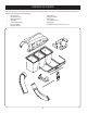
CONTENTS OF CARTON Before beginning installation, remove all parts from the carton to make sure everything is present. Carton contents are listed and shown below. Two hardware packs are included in this kit and are detailed on the following page. • Upper Chute Tube • Grass Catcher Cover • Discharge Chute Elbow • Hitch Bracket Kit (3 Pcs.
CONTENTS OF HARDWARE PACKS This grass collector kit is shipped with two loose hardware packs enclosed. Please check your hardware packs against the illustrations below. The quantities for each item is listed in parenthesis.
ASSEMBLY AND INSTALLATION NOTE: References to left, right, front and rear of the tractor are from the operator’s position, unless otherwise stated. • • NOTE: It may be easier during the mounting stage to leave this hardware only finger tight to facilitate lining up the hitch hole for the clevis pin. You will be instructed to tighten this hardware later in this manual. Before assembly, place the tractor on a firm, level surface, disengage the PTO, stop the tractor engine and set the parking brake.
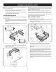
ASSEMBLY AND INSTALLATION 6. Using a 1/2” wrench or socket, secure the hanger assembly to the upright mounting assembly using another (710-0276) carriage bolt from hardware pack 689-00328A and flange lock nut packed in with the upright mounting bracket. See Figure 6. Note: Upon completion of this bagging unit, there will be one(1) extra wing knob from Hardware pack 689-00328A and two(2) carriage bolts and one(1) flange lock nut, that was packed in with the upright mounting bracket.
ASSEMBLY AND INSTALLATION Assembling Remaining Bagger Components 4. Now that the mounting brackets are assembled and are in place on the tractor, follow these steps to assemble the remaining bagger components. 1. Clip in the other side by flexing the screen and pushing it down into the provided cutout hole. See Figure 9.
ASSEMBLY AND INSTALLATION 6. Slide the hinge pin into the hole located on the mounting tab, as in Figure 11. Use the cut-out window (See inset in Figure 11) to line up the hinge pin on the other side and push pin all the way in until it reaches the end-stop. At this point the pin clips into place and is secured by a tab in the bagger cover. See Figure 12. 7.
ASSEMBLY AND INSTALLATION Assembling the Discharge Chute 2 Before installing the discharge chute onto your tractor, a component must first be assembled onto the upper chute tube. The following instructions are for assembling the discharge chute: 1 NOTE: Check the upper chute for a cardboard insert installed for shipping purposes. If the insert is present, remove it before continuing with Step 1. 1.
ASSEMBLY AND INSTALLATION On 50” and 54” Stamped Decks: 6. 1. Raise the deck to its highest position. 2. Remove the deck pin rubber protective cap, 1 in Figure 18. 3. Raise the chute deflector (2 in Figure 18) on the deck and hold it while you install the (731-10133) chute adapter(3), included in hardware pack 68900341, onto the deck as shown in Figure 18. Secure the discharge chute elbow to the cutting deck using a (720-04122) wing knob included in hardware pack 689-00341. Refer to Figure 20.
ASSEMBLY AND INSTALLATION 7. With the bagger cover open, insert the upper chute tube into the discharge chute then pivot the upper chute tube into position so that the chute rests in the upper chute support. See Figure 22. Note: Make sure to align the upper chute with the ridges on the upper chute support.
OPERATION Bagger Operation NOTE: When all of the grass bags are full, place the tractor on a firm, level surface, disengage the PTO, turn the tractor engine off and set the parking brake. 1. Pivot the seat forward and up. 2. Lift up grass bag cover by pushing in on the rear, right-side tab with your right hand, as seen in 1 of Figure 23, and lifting the cover with your left hand in the center rear of the bagger cover, 2. Do not remove the chute tube assembly from the tractor. 2 1 2 Figure 24 4.
TABLE OF CONTENTS Sinstrucciones De Seguridad..............................................................................17 Contenido de la Caja..............................................................................................20 Montaje e Instalación............................................................................................22 Operación..................................................................................................................29 Números de servicio........
INSTRUCCIONES DE SEGURIDAD ADVERTENCIA PELIGRO La presencia de este símbolo indica que se trata de instrucciones importantes de seguridad que se deben respetar para evitar poner en peligro su seguridad personal y/o material y la de otras personas. Lea y siga todas las instrucciones de este manual antes de poner en funcionamiento esta máquina. Si no respeta estas instrucciones podría provocar lesiones personales.
INSTRUCCIONES DE SEGURIDAD 4. Siga las recomendaciones del fabricante sobre pesos y contrapesos de las ruedas, para mejorar la estabilidad. 5. Haga que todos los movimientos en las pendientes sean lentos y graduales. No cambie repentinamente la velocidad ni la dirección. Un frenado o cambio de velocidad repentinos pueden causar que el frente de la máquina se levante y dé una voltereta hacia atrás, lo que podría causar lesiones graves. 6. Evite arrancar o detenerse en una pendiente.
ADVERTENCIA Las pendientes son un factor importante relacionado con un vuelco y renovación de los accidentes que pueden provocar lesiones graves o la muerte. No utilice la máquina en pendientes de más de 10 grados. Todos pendientes requiere mayor precaución. Si no puede retroceder en la pendiente o si se siente inseguro en ella, no la recorte. Siempre corte el césped arriba y abajo las pendientes, nunca en toda la superficie de la cuesta.
CONTENIDO DE LA CAJA Antes de comenzar la instalación, quite todas las piezas de la caja para asegurarse de que todo está presente. Contenido de la caja se enumeran y se muestran a continuación. Dos paquetes de hardware se incluyen en este kit y se detallan en la página siguiente. • • • • • • • • • • • • • Hierba cubierta Catcher Juego de soporte de enganche (3 Pcs.
CONTENIDO DEL PAQUETE DE HERRAJES Este kit colector de hierba se envía con dos paquetes de hardware sueltos cerrados. Se recomienda consultar los paquetes de hardware contra las siguientes ilustraciones. Las cantidades de cada elemento aparece en paréntesis.
MONTAJE E INSTALACIÓN NOTA: Las referencias a izquierda, derecha, parte delantera y trasera del tractor son desde la posición del operador, salvo indicación en contrario. • Antes de armar, coloque el tractor sobre una superficie firme y nivelada, desenganche la toma de fuerza (PTO), detenga el motor del tractor y coloque el freno de mano. • Para mayor comodidad, gire el asiento hacia adelante y déjelo en esa posición hasta que el colector de pasto esté totalmente armado y montado.
MONTAJE E INSTALACIÓN Figure 29 preferencia del operador. 6. Usando una “llave de media o socket, asegurar el conjunto de suspensión a la posición vertical de montaje del conjunto utilizando otro perno (710-0276) el transporte del paquete de tornillería 689-00328A y la brida de la tuerca de seguridad empaquetada con el soporte de montaje vertical. See Figure 30.
MONTAJE E INSTALACIÓN 3. Si no se instala previamente por la fábrica, instale la pantalla del colector de césped en la cubierta de la embolsadora, insertando primero el extremo más cercano al lado que tiene el recorte en el orificio de montaje, como en la Figure 32. Asegúrese de pasar la pantalla por debajo del reborde, como en la Figure 33. Cover mounts in between these two tabs Figure 34 6. Figure 32 4. Calce el otro lado flexionando la pantalla y empujándola dentro del recorte provisto.
AMONTAJE E INSTALACIÓN 7. Instale los cubos en su unidad de soporte insertando primero el borde delantero (1), como se ve en la Figure 38, y bajando el borde posterior hasta que calce en la unidad. 1 2 Figure 36 Abra la cubierta del colector empujando hacia adentro en la lengüeta posterior derecha con la mano derecha, como se ve en 1 de la Figure 37, y levantando con la mano izquierda en el centro de la parte posterior, 2.
MONTAJE E INSTALACIÓN Montaje y configuración del Canal de Descarga 2 Antes de instalar el conducto de descarga en su tractor, un primer componente debe ser montado en el tubo superior de la tolva. Las siguientes instrucciones para el montaje y la configuración del canal de descarga: 1 NOTA: Verifique el canal superior de un inserto de cartón instalado para propósitos de envío. Si el inserto está presente, quite antes de continuar con el Paso 1. 1.
MONTAJE E INSTALACIÓN El 50 “y 54” Enteros Decks 6. 1. Levante la plataforma a su posición más alta. 2. Retire la tapa protectora de goma pin deck, 1 en la Figure 42. 3. Levante el deflector del canal (2 en la Figure 42) en la cubierta y mantenerla mientras se instala el adaptador (731-10133) tolva (3), incluido en el paquete de hardware de 689-00341, sobre la cubierta como se muestra en la Figure 42. Asegure el codo canal de descarga de la plataforma de corte usando una perilla (720 a 04.
MONTAJE E INSTALACIÓN 7. With the bagger cover open, insert the upper chute tube into the discharge chute then pivot the upper chute tube into position so that the chute rests in the upper chute support. See Figure 46. Note: Make sure to align the upper chute with the ridges on the upper chute support.
Operación Bagger Operación 3. NOTA: Cuando ambas bolsas están llenas de hierba, colocar el tractor en una superficie firme y nivelada, desenganche la PTO (enganche de cuchilla), gire el motor del tractor y ponga el freno de estacionamiento. 1. Voltear el asiento hacia adelante. 2. Abra la cubierta de hierba receptor empujando en la, pestaña del lado derecho trasero con la mano derecha, como se muestra en (1) de la Figure 47, y levantando con su mano izquierda en la parte central trasera, (2).
Notes Page This page intentionally left blank. Use this page to make any notes regarding your bagger.
Notes Page This page intentionally left blank. Use this page to make any notes regarding your bagger.
Product questions or problems? 1-888-331-4569 Customer Care Hot Line Get answers to questions, troubleshoot problems, order parts, or schedule repair service. Para respuestas a preguntas o problemas, y ordenar piezas o pedir servicio para la reparación de su equipo. To help us help you, register your product at www.craftsman.com/registration Para poderte ayudar mejor, registra tu producto en www.craftsman.