SEOMU06A-1
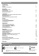
Table of Contents Introduction Symbols and Icons Inventory Preparation / Tools Required 2 3 4 Assembly Rail and Trolley Assembly Installing the Belt Important Installation Instructions Mounting Header Bracket 5 6-7 8 9 Installation Attaching Rail to Header Bracket and Mounting Door Bracket Mounting Opener to Ceiling Attaching Door Arms Installing Light and Emergency Release Handle 10 11 12 13 Wiring Wiring Instructions Connecting Photo Eye Safety System Connecting Door Control Console Connecting Power
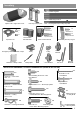
Inventory Rail — Header Segment Rail — Middle Segments x3 Opener Unit + Light Lens Cover Photo Eye Safety System x1 Rail — End Segment with Trolley Stop Bolt x2 Screw #6 x 1” Screw #6 x 1” x2 x1 Two 3-Button Mini Remotes Sprocket Cover Emergency Release Handle + Rope Literature + Safety Labels Wireless Keyless Entry Keypad Door Control Console Trolley Trolley Shaft Drywall Anchor Drywall Anchor Header Bracket Pulley Door Bracket Belt Hanging Brackets Door Arms INSTALLATION HARDWARE,
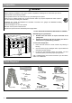
Preparation ! WARNING To prevent SERIOUS INJURY or DEATH: - Before beginning installation of the opener please complete the following test to ensure that your door is balanced and in good working condition. - A poorly balanced door can cause serious injury and damage to the opener. - Always have a qualified garage door service technician make any required adjustments and/or repairs to your door before proceeding with installation.
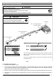
Rail and Trolley Assembly ! WARNING To prevent SERIOUS INJURY: - DO NOT connect power until instructed. - Keep hands and fingers clear from sprocket during operation. - Wear gloves when installing belt. - Keep hands and fingers away from joints and possible sharp edges. ! CAUTION - DO NOT connect power until instructed. - To prevent INJURY, keep hands and fingers away from joints and possible sharp edges. - Wear gloves when installing chain/belt and cable.
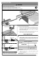
Installing the Belt ! WARNING To prevent SERIOUS INJURY: - DO NOT connect power until instructed. - Keep hands and fingers clear from sprocket during operation. - Wear gloves when installing the belt. - Keep hands and fingers away from joints and possible sharp edges. To Secure the Rail on the Opener With the End Segment of the rail fully inserted into the Rail Bracket, insert a 5/16” x 1-1/2” Clevis Pin through the hole and lock it into position with a Hitch Pin as shown in Fig.1.
Installing the Belt ! WARNING To prevent SERIOUS INJURY: - DO NOT connect power until instructed. - Keep hands and fingers clear from sprocket during operation. - Wear gloves when installing chain/belt and cable. - Keep hands and fingers away from joints and possible sharp edges. 1 2 To Connect and Tension the Belt Sprocket Cover 1. With the trolley positioned against the screwdriver, pull the remaining belt straight along the rail and engage belt teeth around the sprocket.
Important Installation Instructions IMPORTANT INSTALLATION INSTRUCTIONS ! WARNING To reduce the risk of severe injury or death: 1. 2. 3. 4. 5. 6. 7. READ AND FOLLOW ALL INSTALLATION INSTRUCTIONS. Install only on a properly balanced garage door. An improperly balanced door has the potential to inflict severe injury. Have a qualified service person make repairs to cables, spring assemblies, and other hardware before installing the opener.
Mounting Header Bracket ! WARNING To prevent SERIOUS INJURY: - DO NOT connect power until instructed. - The header bracket MUST be SECURELY fastened to the structural support on the mounting wall or ceiling, otherwise the door may not reverse when required. DO NOT install the header bracket over drywall. - Concrete anchors MUST be used when mounting the header bracket into masonry. - NEVER try to loosen, move or adjust garage door springs, cables, pulleys, brackets, or hardware.
Attaching Rail to Header Bracket and Mounting Door Bracket ! CAUTION To prevent SERIOUS INJURY: - DO NOT connect power until instructed. - Horizontal and vertical REINFORCEMENT is needed for fiberglass, aluminum or lightweight steel garage doors BEFORE installing the door bracket. Contact your door manufacturer for reinforcement options. To Attach the Opener to the Header Bracket 1. As shown in Fig.1, use the packaging carton as temporary support for the opener.
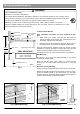
Mounting Opener to Ceiling ! WARNING To prevent SERIOUS INJURY or DEATH: - DO NOT connect power until instructed. - Install the opener at least 7 feet (2.13m) above the floor. - Fasten the opener SECURELY to STRUCTURAL SUPPORTS of the garage to prevent falling. - If installing brackets to masonry, concrete anchors (not provided) MUST be used. To Mount the Opener to Ceiling t ppor ral su u t Struc The three most common installation options are shown in Fig.1-3. Fig.
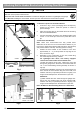
Attaching Door Arms ! WARNING To prevent SERIOUS INJURY: - DO NOT connect power until instructed. - Keep hands and fingers away from the sprocket during operation. - Wear gloves when installing chain and cable. - Keep hands and fingers away from joints and possible sharp edges. Min. 8” (20cm) NOTE: The trolley must be a minimum of 8” (20cm) away from the pulley. 1 Straight Door Arm To Connect Door Arm Follow the steps shown in Fig. 1 1.
Installing Light and Emergency Release Handle ! WARNING To prevent SERIOUS INJURY or DEATH from electrocution: - Disconnect power cord before installing/replacing light bulb. To prevent possible OVERHEATING or damage to opener: - Use ONLY A19 (E26) incandescent bulbs* (100W max.). - DO NOT use short neck or specialty light bulbs. - DO NOT use halogen bulbs. * CFL or LED light bulbs will work but may interfere with hand-held remotes. To install the light: 100W MAX 1.
Wiring Instructions ! WARNING To prevent SERIOUS INJURY or DEATH from electrocution: - Power MUST NOT be connected until instructed. - NO exposed part of the wire should be visible outside of the terminal for proper connection. * VERY IMPORTANT! * Wire from accessories In the following section, the photo eye safety system and push button will be connected to the opener. Please read and understand the wiring instructions before connecting wires. 1.
Connecting Photo Eye Safety System ! WARNING To prevent SERIOUS INJURY or DEATH from electrocution: - Power MUST NOT be connected BEFORE photo eye safety system is connected and aligned. - The opener will not operate until the photo eye safety system is properly connected and aligned. - Install the photo eyes NO higher than 6” (15cm) above the floor. No part of garage door or other objects should obstruct the photo eye safety system during door-closing.
Connecting Door Control Console ! WARNING To prevent SERIOUS INJURY or DEATH from electrocution: - Power MUST NOT be connected until instructed. To prevent SERIOUS INJURY or DEATH from using the push button and a closing door: - Install the push button within sight of the door at a minimum height of 5 feet (1.5m) above the floor. Make sure it is out of the reach of children and moving parts of door and hardware. - NEVER permit children to access the door control console or remote controls.
Connecting Power ! WARNING To prevent SERIOUS INJURY or DEATH from electrocution or fire: - Power MUST be DISCONNECTED BEFORE proceeding with permanent wiring procedures. - Garage door opener installation and wiring MUST be in compliance with all local electrical and building codes. Make sure the opener is ALWAYS grounded. - NEVER use an extension cord, 2-wire adapter or modify the power plug in any way to make it fit the outlet. DO NOT OPERATE OPENER AT THIS TIME.
Travel Limit Adjustment— I. UP Limit ! WARNING To prevent SERIOUS INJURY or DEATH from improper Force Adjustment: - YOU CANNOT adjust force manually to compensate for binding or sticking of the garage door. Call a qualified garage door service person to make necessary adjustments in case of binding. - YOU CANNOT manually increase the force required for closing the door. - After ANY adjustments, Safety Reverse Test MUST be performed to ensure the door reverses on contact with a 1.
Travel Limit Adjustment— II. DOWN Limit ! WARNING To prevent SERIOUS INJURY or DEATH from improper Force Adjustment: - YOU CANNOT adjust force manually to compensate for binding or sticking of the garage door. Call a qualified garage door service person to make necessary adjustments in case of binding. - YOU CANNOT manually increase the force required for closing the door. - After ANY adjustments, Safety Reverse Test MUST be performed to ensure the door reverses on contact with a 1.
Auto Force Adjustment ! WARNING To prevent SERIOUS INJURY or DEATH from improper Force Adjustment: - YOU CANNOT adjust force manually to compensate for binding or sticking of the garage door. Call a qualified garage door service person to make necessary adjustments in case of binding. - YOU CANNOT manually increase the force required for closing the door. - After ANY adjustments, Safety Reverse Test MUST be performed to ensure the door reverses on contact with a 1.5” high object (2x4 laid flat).
Final Adjustments and Testing ! WARNING To prevent SERIOUS INJURY or DEATH from a closing garage door: - The Safety Reversal Test MUST be conducted ONCE A MONTH. - NO ONE should cross the path of moving door during operation and/or testing. - If either force or travel limit adjustment is made, the other adjustment may also needed. - After ANY adjustments to the door system, the Safety Reverse Test MUST be performed to ensure the door reverses on contact with a 1-1/2” thick (2x4 laid flat) object.
Programming 3-Button Remote ! WARNING To prevent SERIOUS INJURY or DEATH: - Keep remote and battery out of reach of children. - NEVER permit children to access the wall panel nor remotes. - Operate the door ONLY when it is properly adjusted, and there are no obstructions present. - ALWAYS keep a moving door in sight until completely closed. NEVER cross the path of a moving door.
Programming Wireless Keyless Entry Keypad To purchase a wireless keyless entry keypad, visit a Craftsman outlet, call 1-888-331-4569, or go online ! WARNING To prevent SERIOUS INJURY or DEATH: - Keep remote and battery out of reach of children. - NEVER permit children to access the wall panel, push button nor remotes. - Operate door only when it is adjusted properly with no obstructions to door travel and is in clear sight. - ALWAYS keep a moving door in sight until completely closed.
Important Safety Instructions IMPORTANT SAFETY INSTRUCTIONS ! WARNING To reduce the risk of severe injury or death: 1. 2. 3. 4. 5. 6. 7. READ AND FOLLOW ALL INSTRUCTIONS. Never let children operate or play with door controls. Keep the remote control away from children. Always keep the moving door in sight and away from people and objects until it is completely closed. NO ONE SHOULD CROSS THE PATH OF THE MOVING DOOR. NEVER GO UNDER A STOPPED, PARTIALLY OPEN DOOR. Test door opener monthly.
Operating the Opener ! WARNING To prevent SERIOUS INJURY or DEATH: - READ AND FOLLOW ALL INSTRUCTIONS AND WARNINGS IN THE OWNER’S MANUAL AND LABELS - Keep remote and battery out of reach of children. - NEVER permit children to access the door control console or remotes. - Operate the door ONLY when it is properly adjusted, and there are no obstructions and is in clear sight. - ALWAYS keep a moving door in sight until completely closed. NEVER cross the path of a moving door.
Door Status vs.
Backup Battery Installation The backup battery is continually charged when the opener is plugged into an electrical receptacle. During a power outage the charged battery enables you to use the opener. AC Power Disconnected 1 5 ~ x2 3 # 8 x 1/2” 4 2 3 3a Motion-sensing Light Installing the Backup Battery: 1. Unplug the power cord from the electrical outlet. 2.
Backup Battery Features Features ● LED indicators showing the battery and status. ● Built-in protection features: over current protection; short circuit ● protection, overload protection, over-voltage protection, over-charge protection. DC power jack for pre-charging or recharging with a plug-in transformer. Specification Dimension (L x W x H) 7.2’’ x 3.9’’ x 1.7’’ Fully Charge Time Suggested 24 hours Recharging Input (DC Jack) 24VDC/1A Cycle life Approx.
Maintenance Schedule Maintenance Door balance test, refer to page 4. Safety reverse test, refer to page 21 Once a month Twice a year Check belt tension ( refer to page 6-7 for adjustment if necessary). Once a year - Limit and force adjustment may be necessary due to weather conditions. Refer to pages 18-20 for adjustment. Conduct safety reverse test after ANY adjustments. - Lubricate door rollers, bearings and hinges.
Troubleshooting TROUBLESHOOTING: Status & Diagnostic Chart - beeps SYMPTOM: Opener does not respond to remote control. ● Check remote control battery. ● Program remote control. ● 2 Beeps: 'Vacation Lock' may be activated on deluxe control (if installed) (Refer to page 22 to program remote control) SYMPTOM: Opener stops before reaching full open/closed position. ● Travel Limit is not properly adjusted. Check adjustment (Conduct safety reverse test after ANY adjustment).
Repair Parts To purchase repair parts, call 1-888-331-4569. Rail Assembly Parts 1 Item Part No. 1 RP-001 Rail—Header Segment 2 RP-002 Rail—Middle Segments 3 RP-003 Rail—End Segment with Stop Bolt 4 GUT-840 Pulley 5 RP-004 Trolley 6 RP-021 Trolley Shaft 7 GUT-410 8 RP-022 Pulley Cover-16T 9 RP-014 Belt Item Part No.
Opener Assembly Parts 11 9 10 1 8 2 3 7 13 4 5 12 7 8 6 Item Part No. 1 N/A 2 3 Chassis GUDT-321 Transformer RP-322 Receiver/Logic Board-BBU 4 GUDT-323 DC Motor 5 GUDT-314 Encoder Module 6 CR-018 7 GUAT-303 Lamp Plate 8 CR-003 Lamp Lens 9 RP-018 Rail Bracket 10 RP-023 Belt Pulley-16T 11 RP-022 Pulley Cover-16T 12 13 32 Name / Description Opener Cover GUDT-319 Battery Holster CR-012 Battery * Should be replaced only by a qualified technician.
CRAFTSMAN WARRANTY 90-DAY IN-HOME LIMITED WARRANTY FOR 90 DAYS from the date of sale this product is warranted against defects in material or workmanship. With proof of purchase a defective product will be repaired free of charge. LIMITED WARRANTY ON PARTS FROM THE 91st DAY THROUGH 3 YEARS from the date of sale this product is warranted against defective parts. With proof of purchase a new part will be furnished to replace a defective one free of charge.