perator's I:RnFrSMAN° T1200 LAWN TRACTOR 420cc, Variation 42" Deck Speed Model No. 247.203721 • Espanol, P. 36 This product has a low emission engine which operates differently from previously built engines. Before you start the engine, read and understand this Operator's Manual. For answers to your questions this product, call: Before using this equipment, read this manual and follow 1-888-331-4569 all safety rules and operating instructions.
Warranty Statement .......................................................... Safety Instructions ............................................................ Slope Gauge ..................................................................... Assembly ........................................................................... Operation ........................................................................
This symbol points outimportantsafety instructionswhich,if not followed, could endangerthe personalsafetyand/orproperty of yourselfandothers. Readandfollow all instructionsin this manual beforeattempting to operate this machine.Failureto complywith these instructionsmay resultin personalinjury.
Check overhead clearances carefully before driving under lowhanging tree Do Not: branches, wires, door openings etc., where theoperator may bestruck or Donot turn on slopesunlessnecessary; then,turn slowlyandgradually pulled from themachine, which could result inserious injury. downhill,if possible. Disengage allattachment clutches and depress thebrake pedal completely Donot mow neardrop-offs,ditchesor embankments. Themowercould before attempting tostart engine.
Onslopes,the weightof the towedequipmentmaycauselossof tractionand lossof control. Alwaysuseextracautionwhentowing with amachinecapableof making tight turns(e.g."zero-turn"ride-onmower).Makewideturnsto avoid jack-knifing. Travelslowlyandallowextradistanceto stop. Donot coastdownhill. SERVICE Safe Handling of Gasoline: Toavoid personalinjuryor property damageuseextreme carein handling gasoline.Gasolineisextremely flammable andthe vaporsareexplosive.
DO NOT MODIFY ENGINE Toavoid seriousinjuryor death,do not modify engine in any way.Tampering with the governorsetting canlead to a runawayengine andcauseit to operateat unsafespeeds.Nevertamperwith factory setting of engine governor.
SAFETY SYMBOLS This page depicts and describes safety symbols that may appear on this product. Read, understand, and follow all instructions on the machine before attempting to assemble and operate. P I I I READ THE OPERATOR'S MANUAL(S) Read, understand, and follow all instructions in the manual(s) before attempting to assemble and operate DANGER-- ROTATING BLADES Never carry passengers. Never carry children, even with the blades off.
X 15° Slope (OK) 15° Slope (TOO STEEP) '_. _ Figure 1 Figure 2 15° dashed line USETHISSLOPEGAUGETODETERMINE IF A SLOPEIS TOOSTEEPFORSAFEOPERATION! To checkthe slope, proceedas follows: 1. Removethis pageand fold along the dashedline. 2. Locatea verticalobject on or behindthe slope (e.g. a pole, building,fence, tree, etc.) 3. Align eitherside of the slope gaugewith the object (See Figure1 and Figure2 ). 4. Adjust gaugeup or down until the left cornertouchesthe slope (SeeFigure1 and Figure2). 5.
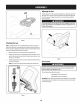
IMPORTANT: Yourtractorisshippedwith motoroffin the engine.However,you MUSTcheckthe oil levelbeforeoperating.Referto the Service& Maintenance sectionforinstructionson checkingthe oil level. Shipping BraceRemoval Attaching the Battery Cables Makesurethe riding mower'sengineisoff, removethe ignitionkey,and set the parkingbrake before removingthe shipping brace.Referto the jOperaton sect on for nstruct ons on howto set the park ng brake.
F Adjustingthe Seat Toadjustthe positionof the seat,pull upandholdthe seatadjustmentlever.Slide the seatforwardor rearwardto the desiredposition;thenreleasethe adjustment lever.Makesureseatislockedintopositioninaseat-stopbeforeoperatingthe tractor.SeeFigure5. Beforeoperatingthe tractor, makesurethe seat isengaged ina seat-stop. Engagethe parkingbrake.Stand behindthe machineand pull backon seat until it clicksintoplace.
B A C .I D © H F G Rgure6 A ParkingBrakeLever F PTOLever(BladeEngage) B Throttle/ChokeControlLever G CupHolder C IgnitionSwitchModule H ShiftLever D Auto-drivePedal I SeatAdjustmentLever E DeckLift Lever J BrakePedal NOTE: Anyreference inthismanual totheRIGHT or LEFT sideofthetractorisobserved fromoperator's seatposition facingforward towards thefrontoftractor. Meets ANSiSafetyStandards CraftsmanTractorsconformto the safetystandardof the AmericanNationalStandardsInstitute (ANSI).
ParkingBrakeLever Seat AdjustmentLever Tosetthe parkingbrake:Fullydepressthe brakepedal.Movethe parkingbrakeleverinto the parkingbrakeposition.Release the brakepedalto allowthe parkingbraketo engage. Theseatadjustmentleverislocatedbelowthe front/left of theseat.Thelever allowsforadjustmentof the foreandaft positionof the seat.Referto the Assembly sectionof the manualformoredetailedinstructionsforadjustingthe seatposition.
Gasand Oil Fill-up Oil iMPORTANT: Yourtractorisshippedwith motoroil intheengine.However,you MUSTcheckthe oil levelbeforeoperating.Becarefulnotto overfill. Forinstructionsonhowto checkthe engineoil,referto CheckingTheEngineOilin the ServiceandMaintenance sectionof thismanual. Gasoline Thegasolinetank islocatedunderthe hood.Donotoverfill. Useextreme carewhen handling gasoline.Gasolineisextremelyflammable andthe vaporsareexplosive.Neverfuel machineindoorsor while the engine ishotor running.
Withthe ignitionkeyinthe NORMAL MOWING position,the electricPTO (BladeEngage) clutchwill automaticallyshutoff if the PTO(BladeEngage) knobis movedinto the engaged(ON)positionwiththe drivepedalin positionfor reversetravel. NOTE:Thedeckwheelsareananti-scalpfeatureof the deckandarenot designed to supportthe weightof the cuttingdeck.Referto Levelinginthe Maintenance and Servicesectionof thismanualformoredetailedinstructionsregardingvariousdeck adjustments.
Light "v,,"_ 1. Depressthe brakepedalto releasethe parkingbrakeandthen letthe pedal up. Reverse 2. Movethe throttle leverintothe FAST (rabbit)position. 3. Placethe shift leverineitherthe FORWARD or REVERSE position. Mode Position 5. z_ G R F Caution IMPORTANT; DoNOTusethe shift levertochangethe directionof travelwhenthe tractorisinmotion.Alwaysusethe brakepedalto bringthe tractorto acomplete stopbeforeshifting. 4.
Engaging the Blades Mowing Engagingthe PTO(BladeEngage) transferspowertothe cuttingdeckor other (separatelyavailable)attachments.Toengagethe blades,proceedasfollows: Tohelp avoid bladecontactor athrown object injury,keepbystanders, helpers,children andpets at least 75feet from the machinewhile it is in operation. Stopmachineif anyoneentersthe area. I. Movethe throttle/chokecontrolleverto the FAST (rabbit)position. 2.
MAINTENANCE SCHEDULE Beforeperforminganytype of maintenance/service,disengageall controls andstop the engine.Wait until all moving partshavecometo a complete stop.Disconnect sparkplug wire andgroundit againstthe engine to prevent unintendedstarting. Alwayswearsafety glassesduring operationor while performing anyadjustments or repairs. BeforeEachUse Followthe maintenance schedulegivenbelow.Thischartdescribes service guidelinesonly.Usethe ServiceLogcolumnto keeptrackofcompleted maintenance tasks.
Checkingthe Engine Oil Changing the Engine Oil and Filter Onlyusehighqualitydetergentoil ratedwith APIserviceclassification SF,SG, SH,or SJ.Selectthe oil'sSAEviscositygradeaccordingto the expectedoperating temperature.Followthechartbelow.Althoughmulti-viscosityoils (5W20,10W30, etc.)improvestartingin coldweather,theywill resultinincreasedoil consumption whenusedabove32°I.Checkyourengineoil levelmorefrequentlyto avoidpossible enginedamagefrom runninglowon oil.
f Beforereplacingthe fuel filter,drainthe fuel tank.Otherwise,fuelcanleak out andcauseafire orexplosion. ToDrainthe fuel: Locatethe fuelfilter,seeFigure11,whichisroutedonthe left sideof the enginebetweenthe fueltankandthecarburetor,andmaybeattachedto the enginewithatie strap.Cutthetiestrap,if present,thenpinchthe tabsonthe in-lineclamponthefuel filterwith apairof pliers,slidethe clampupthe fuel line.Pullthe fuellinefreefrom thefilter andplacethe openendof thelineinto anapprovedcontainertodrainthe fuel.
Air Cleaner Removethefoampre-filterfrom aroundthe paperairfilter. SeeFigure 16.Replace paperelementwhendirty or damaged.Cleanfoamelementor replacewhendamaged. Paperfilters cannotbecleanedandshouldbe replacedevery100operatinghours; moreoftenif usedin extremelydustyconditions. Neverusegasolineor low flash point solventsfor cleaningthe air filter element.A fire or explosioncould result. IMPORTAfl# Neverruntheenginewithouttheairfilter.Rapid enginewearwill result. 1.
6. Attachthe airfilter cover,makingsureto alignplasticrib featuresonthe shroudto the plasticfeatureson the airfilter cover.SeeFigure18.Turn thumbscrewsclockwiseuntilsnug.Checkfor anymisalignment. Measurethe plug gapwith afeelergauge.Correctasnecessary bybending sideelectrode.SeeFigure20.Thegapshouldbesetto 0.024-0.031in. Electrode Air Filter Cover Plastic Feature Figure20 4. Checkthatthe sparkplugwasherisingoodconditionandthreadthe spark plug inby handto preventcross-threading. 5.
Lubrication Beforelubricating,repairing,or inspecting,alwaysdisengagePTO(Blade IMPORTANT: Theuseofa pressure washerto cleanyourtractorisNOT recommended. It maycausedamageto electricalcomponents,spindles,pulleys, bearingsorthe engine. I EngageLever),moveshift leverintoneutral position,set parkingbrake,stop I eng ne andremovekeytopreventun ntendedstart ng. l | Pivot Points & Linkage Ascrewanddeckplug canbefoundonyourtractor'sdecksurfaceasseenin Figure 21.
3. Locate theflangelocknutonthefrontsideofthestabilizer bracket. See Figure 22. Retightenthe hexcapscrewon the left deckhangerbracketwhenproper adjustmentisachieved. Tighten theflangelocknuttoraisethefrontofthedeck; Loosen theflangelocknuttolowerthefrontofthedeck. r ! Hex Cap Screw Figure23 SeatAdjustment Referto the Assemblysectionof thismanualforseatadjustmentinstructions.
f Cutting Deck Removal /// To remove the cutting deck, proceed as follows: 1. Placethe PTO(BladeEngage)leverinthe disengaged(OFF)positionand engagethe parkingbrake. 2. Lowerthe deckbymovingthe decklift leverinto the bottomnotchon the rightfender. 3. Removethe self-tappingscrew(A)thatsecuresthe belt-keeperrodfrom aroundthe tractor'sPTOpulley,thenremovethe belt keeperrod(B).See. Note: Makeamentalnotewhat holethe otherendof the belt-keeperrodis insertedinfor reinstallationpurposes. 4.
3. 4. Connectthe secondcable(negative-) to the otherpostof thejumper battery. Connectthe otherendof the negativecableto theengineblockof the tractor,awayfrom the battery.Attachto anunpaintedpartto assureagood connection. If the jumperbattery isinstalledon avehicle(i.e. car,truck),do NOTstart the vehicle'senginewhen jump starting your tractor. 5. Startthe tractor(asinstructedearlierinthissectionof thismanual). 6. Setthe tractor'sparkingbrakebeforeremovingthe jumpercables,inreverse orderof connection.
CuttingBlades If the cutting edge of the bladehaspreviouslybeensharpened,or if any metalseparationispresent,replacethe bladeswith newones. Shutthe engine off andremoveignitionkeybefore removingthecutting blade(s)for sharpeningor replacement.Protectyour handsby using heavy [g oveswhen grasp ngthe bade. A poorlybalancedbladewill causeexcessivevibration, maycausedamageto the tractorand/or resultin personalinjury. Periodicallyinspectthe bladeand/or spindlefor cracksor damage, 5.
10. Whileholdingthe belt andpulleytogether,rotatethe pulleyto the left. Continueholdingandrotatingthe pulleyandbeltuntil the belt isfully rolled into the PTOpulley. ParkingBrakeAdjustment Changingthe Transmission Drive Belt NOTE:Several components must be removed and special tools (ie air/ impactwrench) in order to change the tractor's drive belt. Contact the nearest Parts & Repair Service Center to have your transmission drive belt serviced.
Neverstore lawn tractor with fuel in tankindoorsor in poorlyventilated areaswhere fuel fumes may reachanopen flame, spark,or pilot light ason a furnace,water heater, clothesdryer,or gasappliance. PreparingTheEngine DrainingThe Fuel IM PORTANT: Fuelleft inthe fueltank duringwarmweatherdeterioratesand will causeseriousstartingproblems. 1. Locatethe fuel filter,whichis locatedonthe left sideofthe engine,andmay beattachedto the enginewith a tiestrap.
Enginefails to start 1. 2. PTO/BladeEngageleverengaged. Parkingbrakenotengaged. 1. 2. Placeleverin disengaged(OFF) position. Engageparkingbrake. 3. 4. 3. 4. Connectwire(s) to sparkplug(s). PlaceThrottle/Chokeleverintothe FASTposition. 5. Sparkplugwire(s) disconnected. Throttle/Chokecontrollevernot in correct startingposition. Chokenotactivated 5. MovetheThrottle/Chokeleverintothe Choke position. 6. 7. Fueltank empty,or stale fuel. Blockedfuel line. 6. 7.
This page intentionally left blank. Use this page to make any notes regarding 3O your tractor.
FEDERAL and/or CALIFORNIA EMISSIONCONTROL WARRANTYSTATEMENT YOURWARRANTYRIGHTSANDOBLIGATIONS MTD Consumer Group Inc, the United States Environmental Protection Agency (EPA), and for those products California, the California Air Resources Board (CARB) are pleased to explain the emission (evaporative and/or warranty on your 2013 and later small off-road spark-ignited engine and equipment (outdoor equipment engines must be designed, built and equipped to meet the State's stringent equipment engine
10. Add-on ormodified partsthatarenotexempted bytheAirResources Board maynotbeused. Theuseofanynon-exempted add-on or modified partsbytheultimate purchaser willbegrounds fordisallowing awarranty claims. MTDConsumer Group Incwillnotbeliable to warrant failures ofwarranted partscaused bytheuseofanon-exempted add-on ormodified part.
Congratulations on making a smart purchase. Your new Craftsman® product is designed and manufactured for years of dependable operation. But like all products, it may require repair from time to time. That's when having a Repair Protection Agreement can save you money and aggravation.
Operaci6n segura Pr,_cticas .......... Asamblea ........................... Operacion de ...................... De Servicio y Mantenimiento de ....... Paginas Page Paginas Paginas CRAFTSMAN 35 41 43 47 Fuera de temporada de almacenamiento .. Page 55 Soluci6n de problemas ................ Page 56 Reparaci6n de Acuerdo de Protecci6n .... Page 59 Servicio de nOmeros ............
Esta rn_.quina rue construidapara seroperadade acuerdocon las reglasde seguridadcontenidasen este manual.AI igualque concualquiertipo de equipo rnotorizado,un descuidoo error por partedel operadorpuedeproducirlesionesgraves.Esta rn_.quina es capazde arnputarrnanosy piesy de arrojarobjetoscon gran fuerza.Deno respetarlas instruccionesde seguridadsiguientesse puedenproducirlesionesgraveso la rnuerte.
• • • • • • • • Nuncadeje la rn_.quina en funcionarniento sinvigilancia.Apague siernprelascuchillas,coloqueel frenode rnano,detengael motory retirela Ilaveantesde bajarsedel vehiculo. Tengasurnocuidadoal cargaro descargarla rn_.quina en un rernolqueo carni6n.Estaunidadno debeconducirseen ascensoo descensode rarnpas,porquepodrialadearsey provocarlesiones personalesgraves.En las rarnpasla rn_.quina sedebe ernpujar rnanualrnente paracargarlao descargarlacorrectarnente.
• Paraevitaraccidentesal operaren rnarchaatr_.s,siernpredesenganchelascuchillasantesde colocarrnarchaatr_.s.Siest,. instalado, el "ModoPrecaucidnMarchaAtr_.s"(hojasde operarla rn_.quina, rnientrasquelospaseosa la inversa)no debeutilizarsecuandohay ni_osu otraspersonaspresentes. • Mantengaa losni_osalejadosde losrnotoresen rnarchao calientes. Puedensufrirquernaduras conun silenciadorcaliente. • Retirela Ilavecuandodeje la rn_.quina sinvigilancia,evitequeuna personasinautorizaci6nla rnaneje.
• • • NO MODIFIQUE Reviselos pernosde montajede la(s) cuchilla(s)y del motora intervalosfrecuentespara verificarque est6n bien apretados. Adem_.s,inspeccionevisualmentela(s) cuchilla(s)en buscade daSos(por ejemplo,desgasteexcesivo,abolladuras,rajaduras, etc.). Reemplacela(s) cuchilla(s)Qnicamentecon lascuchillas de fabricantesde equiposoriginales(O.E.M.)listadasen este manual.El usode piezasque no cumplencon las especificacionesdel equipooriginal podriatenercomo resultadoun rendimientoincorrectoy adem_.
SJlVlBOLOS DE SEGURIDAD Esta p&ginarepresentay describela seguridadlos simbolosque puedenpareceren este producto.Lea,comprenda,y sigatodas instrucciones en la m_quinaantesprocurarpara reuniry operar. LEA EL MANUAL(S) DEL OPERADOR leido, entienda, PELIGRO-- y siga todas las instrucciones en el manual(s) antes de procurar montar y funcionar DE EL CORTE DE PIE Nunca transporte pasajeros. Nunca transporte ni_os, aun con la cuchilla apagada. 0 PELIGRO-- DE EL CORTE DE PIE Retroceda lentamente.
X I5 ° Pendiente (DEMASIADO ESCARPADO) (ACEPTAR) • 15° Pendiente Figura1 Figura 2 4_ "'" USO DE ESTE PENDiENTE DE CALIBRE PARA DETERrvIINAR SlUNA PENDIENTEES DEIVlASIADO ESCARPADO PARA UNA OPEBACION SEGURA! Para comprobar la pendiente, haga Io siguiente: 1. Borrar esta p_gina y doble a Io largo de la linea discontinua. 2. Localizar un objeto vertical sobre o detr_.sde la pendiente (un poste, un edificio, una valla, un _.rbol,etc.) 3.
EnvioBraceeliminad6n IMPORTANTE: Sutractorseentregaconaceitede motorenel motor.Sinembargo, debecomprobarel niveldeaceiteantesdeoperar.Consultelasecci6ndeServicio y Mantenimientoparaobtenerinstrucciones sobrelacomprobaci6n delnivelde aceite. Aseguresede clueel motor del tractor cortacdspedes,retire laflare de encendido,y porterel freno antesde quitarlaflare deenvio.
f NOTA: Eltractornofundonaconelcabledealimentaci6n desconectado. Ajustedelasiento Paraajustarlaposici6ndelasiento,tirelohadaarribay sostengalapalancade ajustedel asiento.Desliceelasientohadaadelanteo haciaatr_salaposid6n deseada;luegosueltelapalancade ajuste.Asegurese de queelasientoest#trabado en untopedeasientoantesde operareltractor. Veala Figura5. J J! ...... /f Antesdeoperar eltractor, aseguresede queel asientoest_ enganchadoen el tope del asiento.Coloqueelfreno de mano.
A C J D © E H F G J Figura6 A Palancadelfrenodeestacionamiento F Tomadefuerzadepalanca(BladeEngage) B Aceleradory palancadecontrolde Choke G Portavasos C IgnitionSwitchModule H DeVelocidad D Auto-discopedal I Palancade ajustedelasiento Levantelapalancadelacubierta J Pedalde freno E NOTA: CualquierreferenciahechaenestemanualalladoDERECH0 o IZQUIERD0 deltractordebeentendersetal comoseobservadesde laposici6ndeloperador.
Freno de estacionarniento Palancade ajuste dei asiento Paraajustarelfrenodeestacionamiento: completamenteelpedal de freno.Moverlapaiancadelfrenodeestacionamiento en la posid6ndel frenodeestadonamiento. Sueiteelpedalde[freno paraqueelfrenode estadonamientoa participar. Lapalancadeajustedelasientoseencuentradebajode lapartefrontal/izquierda delasiento.Lapalancapermiteelajustede lapartedelanteray laposid6n longitudinaldelasiento.
Nuncalleneenexcesoeldep6sitodecombustible.Lleneeltanqueno m_s de I/2pulgadapordebajodelabasedelcuellodeltap6ndecarga,paradejar espadoparalaexpansi6ndelcombustible. La palanca de cambio Lapalancade cambiosest4situadaenel ladoizquierdode ladefensay tienetres posiciones, FORWARD, neutraly REVERSE. Elembrague-pedal defrenodebeestar deprimidoy eltractornodebeestar enmovimientocuandolapalancade cambiosen movimiento. IMPORTAIVTE: fuercelapalanca decamblos.
Acdonadoel freno de estacionamiento Paraactivar el freno de estadonamiento: Evitelesionespersonales graveso la muerte Enlaspendientesconduzcahadaarribay hadaabajo,node formatransversal. Evitemaniobrasdegirobruscas. Nooperela unldaden _reasdondepuedederraparo ladearse. S[lam_qulnadejadesubirlapedientedetengalascuchlllasy retrocedalentamentebajandolapendlente. Nocorteelc#spedcuandohayaniffosu otraspersonascerca. Nuncatransportenlffos,n[siquierasl lascuchlllasest_n desconectadas. I.
Arranquedei motor 2. Moverlapalancadelaceleradorenel FAST (conejo)laposici6n. 3. Coloquelapalancadecambiostantoen laposici6ninversa o FORWARD. IMPORTANTE: NOintentecambiarladirecci6ndelamarchacuandoeltractorest_ Nohagafuncionar el tractor, si el sistemade bloqueono funciona correctamente.Estesistemafue diseffadoparasuseguridady protecci6n. en movimiento.SiempreIleveeltractora unaparadacompletaantesde moverla palancadecontroldeveloddadhaciaadelanteaatr_soviceversa.
Involucrara losBlades PartJdpad6n delatomadefuerza(BladeEngage) lastransferendas deenergiaala plataformadecorteo deotrotipo(dJsponible porseparado) losarcNvosadjuntos.Para partkiparde lashojas,hagaIosiguiente: 1. Moverlapalancade controldelaceleradora lar_pida(conejo)laposid6n. 2. Sujetelatomadefuerza(BladeEngage) y girar lapalancade todoel camino aseguiralosnovios(ON)laposki6n. 3.
Mukhing Faros Unkit paraabonoest4disponiblecomoun archivoadjunto.Mulchingesun proceso derecirculad6nhlerbacortadavariasvecespordebajode laplataformadecorte. Losultra-finasrecortessevenobllgadosde nuevoenelc_speddondeactuancomo unfertillzantenatural. Unkit paraabonosepuedecompraratrav_sdel puntodeventaenelqueadquH6 estetractor.Paraobtenerm&sinformaddn,s61otienequeponerseen contactocon Searsal 1-800-659-5917.
LISTADEMANTENIMIENTO Antesderealizarcualquiertipo del mantenimiento/servicio,sueitetodoslos mandosypare el motor. Esperehastaquetodaslaspartesde movimiento hayanvenido a unaparadacompleta.Desconecteel alambrede bujia y b_selocontrael motor para prevenirel comienzoinvoluntario. Siemprelleve puestoscristalesinastillablesdurante la operaci6no realizandocualquier ajusteo reparaciones. Antesdecadauso Sigalalistademantenimientodadaabajo.Estacartadescribepautasdeservicio s61o.
Mantenimiento del motor Comprobar el aceite Cambio de aceite motor y filtro del motor 561oelusodeaceitede altadetergenteseevalu6lacalidadconlaclasificaci6n deservicioAPI,5F,5G,5H,o SJ.5eleccione elaceitedegradodeviscosidadSAEde acuerdocondelatemperaturadefuncionamiento.5igalatabladeabajo.Aunque variosdelosaceitesdeviscosidad(5W20,IOW30,etc)mejorarlapartidaenclima frio,quesetraducir_ienelconsumodepetr61eoaumentacuandoutilizadopor encimade32oF.
Laspiezasde recambiodebeserlamismaeinstalados en lamismaposici6n quelaspiezasoriginales. Sisederramacombustible,esperehastaqueseevaporaantesdearrancarel motor. Antesde reemplazar el filtro decombustible,vaciareltanquede combustible.DeIocontrario,elcombustiblepuedefiltrarsey provocarun incendio o unaexplosi6n. Para drenar el combustible: 1. Para cambiar el filtro de combustible: Oil Filter 1. Figure 39 12. 13.
1. Desatornillelostornillosy retirelacubiertadelfiltro deaire.Yeala Figure41. Air Filter, Air Filter Figure43 4. Tocleanfoamelement,washina mildliquiddetergentandwater.Squeeze or pressthe foamelementto rinseout dirt andwater.Donot twist;this coulddamageor tearthe foamelement.Allowto dry thoroughlybefore using.DONOToil thefoamelement. 5. Attachthe newair filter with foamelement,aligningthe holein the airfilter with the intakemanifold.SeeFigure44. Figure41 2. Retireelfiltro deaire.Veala Figure42.
Electrode Air Cover Filter Plastic Feature Figure 47 4. Compruebe quelaarandeladelabujiaest_en buenascondidonesy enrosquelabujiaamanoparaevitarquelarosca. 5. Despu_s dehaberseasentadalabujia,aprieteconunaIlavede buj[apara comprimirlaarandela. Nota:AIinstalar unabujianueva,apriete1/2vueltadespu_squela bujia seasientaparacomprimirlaarandela.Cuando vuelvaa instalar unabuj[a usada,apriete1/8-1/4vueltadespu_s de losasientosdela buj[apara comprimirlaarandela.
Lubrkad6n kimpieza de las m_quinas y la cubierta CualquJer combustibleoaceJtederramadoen lam_quJna debeserborradode JnmedJato. NOpermJtaquelosdesechos queseacumulanalrededordelasaletasde refrJgeraddn delmotoroencualquJer otra partedelam_quJna. Antesde lubricantes,reparaci6no inspecci6n, siempredesconectartoma de fuerza,palancadecambiosepongaen poski6n neutral, el freno demano, apagueel motor y quitelaIlave paraevitar elarranque nodeseado.
1. Coneltractorestadonadoenunasuperfidefirme y nivelada,coloquela palancadeelevaci6ndelaplataformaen lasegundaa laprimeracategoffa (segundaposici6nm_salta),y girelahojaIom_scercadelcanaldedescarga queesparaleloaltractor. 2. Medirladistanciadesdela partefrontaldela puntadela palaenelsueloylapartetrasera delapuntadelapalaenelsuelo.Laprimeramedidatomadadebeestarentre 1A"y3/ 8"menosdelasegunda medici6n.Determinar ladistandaaproximada necesaria paraunbuenajustey proceder, sifueranecesario, elsiguiente paso.
Retiree[ pasadorde[apajarita,asegurar[avari[[adeestabi[izadorde[a p[ataformaa [acubierta.Des[icee[tiradorde[acubiertade[soporteen[a cubiertacomosemuestraenla Figure53. Evite[as[esionespellizcos.Nuncacoloquesusdedosen [a primaveraociosoo entre [acorreay unapolea, mientrassequitae[ cintur6n. f Z ZZZZ_ C cZZZZZ_ LZZLZ ......... I ..... J Figure53 Figure51 5. 7. Retireconcuidadoel cablede[PTOde [aparteposteriorde [aplataformade torte quitandoel pasadordecorbatade lazoqueIoasegura.
Neum_tkos Carga Nosobrepasarnuncala presi6nm_xima deinfladoqueapareceen la pared lateraldela Ilanta. Bateriasemiten un gasexplosivodurante lacarga.Cargade la bateriaen un _reabien ventilada y mantenerselejosde unallama abierta o piloto comoen un calentadordeagua, estufa, homo,secadorade ropao de otros aparatosde gas.
Utiliceuna flare de parpara apretar latuercade husillo de la hoja brida hexagonalaentre 70 libras-piey 90 libras-pie. Decambiar la correade cubierta Aseguresede queapagueel motor, quitarlaflare deencendido,desconecte [el cablede la buj[a (s)y tierra contrael motor paraevitar involuntaria de LPartidaantesde quitarel dntur6n. Todoslosdnturones en sutractor est_nsujetosadesgastey debenset reemp azadosen casode cua quer s gnode desgasteest_npresentes.
Cubierta de la correa Figure57 62
Nuncaalmacenetractor de c_spedcon combustibleenel tanque en un espaciocerradooen _reasconpocaventilaci6n, dondelosgasesdel combustiblepuedanakanzar elfuego, chispaso una luzpiloto comola que tienen algunoshornos,calentadoresde agua,secadoresde ropa oalgun otro dispositivoagas. Extraigalabujiay viertauna(1)onzadeaceiteparamotorporelorificio delabujiaenelcilindro.Hagagirarel motorvariasvecesparadistribuirel aceite.Vuelvaacolocarlabuj[a.
El motor El motor err_fitica El motor El motor no arranca funciona de manera recalienta vacila a altas 1. Perilla de potencia conectada. 2. No est_ficolocado 3. Se ha desconectado 4. La palanca de control del regulador no est,1 en la posici6n de arranque correcta. 5. No se ha activado 5. Tire el control 6. El dep6sito de combustible combustible se ha echado 6. Llene el dep6sito con gasolina menos de 30 dias). 7. La linea del combustible est_fi bloqueada. 7.
DECLARACI6N FEDERAL y/o DECALiFORNiA SOBREGARANTiASENELCONTROL DEEMISIONES SUSDERECHOS Y OBLIGACIONES ENCUANTOA LAGARANTiA MTD Consumer Group Inc, la Agencia venta en el estado de California, de Proteccidn el Departamento al sistema de control (ECS) de emisiones chispa para todo terreno, peque_o, encendido (evaporativas de exteriores deben estar dise_ados, construidos del aho 1997 y modelos posteriores m_is abajo, siempre y/o de escape) de su equipo del a_o 2013 y ahos posteriores peque_os el
6. Elpropietario delmotordeequipos deexteriores nodeber_ pagar eltrabajo dediagndstico directamente asociado conunapieza garantizada defectuosa enrelaci6n conlasemisiones, siempre ycuando dichotrabajo dediagn6stico serealice enuncentro cubierto pot lagarantia. 7. MTDConsumer Group Incesresponsable potdahos causados aotroscomponentes demotores oequipos derivados delafallabajo garantia decualquier pieza garantizada. 8.
Felicitaciones por haber realizado una adquisici6n inteligente. El producto Craftsman® que ha adquirido esta diseSado y fabricado para brindar muchos aSos de funcionamiento confiable. Pero como todos los productos a veces puede requerir de reparaciones. Es en ese momento cuando el disponer de un Acuerdo de protecci6n para reparaciones le puede ahorrar dinero y problemas.
Riding Equipment questions or problems? Satisfaction with your purchase is our number one concern! To troubleshoot problems, get answers to questions, order parts, or schedule repair service for your Riding Equipment, call the number below. Para respuestas a preguntas o problemas, y ordenar piezas o pedir servicio para la reparacibn de su equipo, Ilame el nt_mero abajo. 1-800-659-5917 Craftsman Help Line www.craftsman.