perator's I:RnFrSMRN° LAWN TRACTOR 19.5 HI:), 42" Deck Electric Start, 7 Speed Model No. 247.28902 • Espanol, P. 59 This product has a low emission engine which operates differently from previously built engines. Before you start the engine, read and understand this Operator's Manual. For answers to your questions this product, Call: Before using this equipment, read this manual and follow 1-800=659=5917 all safety rules and operating instructions.
Off-Season Storage ........................................................ 27 Trou bleshooting .............................................................. 28 Labels ............................................................................. 29 Parts List ......................................................................... 30 Espafiol ............................................................................ 59 Service Numbers .............................................
This machinewas builtto be operatedaccordingto the safeoperation practicesin this manual.As with anytype of powerequipment, carelessnessor error on the partof the operatorcan resultin serious injury.This machineis capableof amputatingfingers,hands,toes and feet and throwingdebris.Failureto observethe followingsafety instructionscouldresultin seriousinjuryor death. This symbolpointsout importantsafetyinstructionswhich,if not followed,couldendangerthepersonalsafetyand/orpropertyof yourselfand others.
• SLOPE Slowdownbeforeturning.Operatethe machinesmoothly.Avoid erraticoperationand excessivespeed. Disengageblade(s),set parkingbrake,stopengine and wait until the blade(s)come to a completestop beforeremovinggrass catcher,emptyinggrass,uncloggingchute,removinganygrass or debris,or makinganyadjustments. OPERATION Slopesare a majorfactorrelatedto loss of controland tip-over accidentswhichcan result in severeinjuryor death.All slopes require extra caution.
CHILDREN SERVICE Tragicaccidentscanoccur ifthe operatoris notalert to the presence of children.Childrenare often attractedto the machineand the mowing activity.They do notunderstandthe dangers.Neverassumethat childrenwill remainwhereyou last sawthem. • Keepchildrenout of the mowingareaand inwatchfulcare of a responsibleadultotherthanthe operator. • Be alert and turnmachineoff ifa childentersthe area. SafeHandlingof Gasoline Toavoidpersonalinjuryor propertydamageuse extremecarein handlinggasoline.
General Service • Donot changethe enginegovernorsettingsor over-speedthe engine.The governorcontrolsthe maximumsafe operatingspeed • Never runanengine indoors orina poorly ventilated area.Engine of the engine. exhaust contains carbon monoxide, anodorless, anddeadly gas. Maintainor replacesafetyand instructionlabels,as necessary. • Before cleaning, repairing, orinspecting, make certain the blade(s) andallmoving partshave stopped.
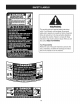
SAFETY SYMBOLS This pagedepictsand describessafety symbolsthat may appearon this product. Read,understand,and follow all instructions on the machine beforeattemptingto assembleand operate. READ THE OPERATOR'S MANUAL(S) Read, understand, and follow all instructions in the manual(s) before attempting to assemble and operate DANGER-- ROTATING BLADES Never carry passengers. Never carry children, even with the blades off.
Sight and hold this levelwith a vertical tree... | I | | I | i or a corner of a building... | | 0o 15 ° Use this page as a guide to determine slopes where you may not operate safely. Donot operateyourlawnmoweron such slopes.Do notmow on inclineswith a slope in excessof 15degrees(a rise of approximately2-1/2feet every 10feet). A riding mowercouldoverturnand causeseriousinjury.Operateriding mowersup and downslopes,neveracrossthe face of slopes.
ROTATING BLADES CAUSE SERIOUS INJURY OR DEATH DONOTMOWWHENCHILDREN OROTHERS ARE AROUND NEVER CARRY CHILDREN EVEN WITHBLADE(S) OFF. LOOK DOWNANDBEHIND BEFORE ANDWHILE BACKING. MOWING INREVERSE ISNOTRECOMMENDED. WARNING This symbol points out important safety instructions which, if not followed, could endangerthe personal safety and/or property of yourself and others. Read and follow all instructions in this manual before attempting to operate this machine.
IMPORTANT:Yourtractoris shippedwith motoroil in theengine. However,you MUSTcheckthe oil levelbeforeoperating.Referto the Service& Maintenancesectionfor instructionson checkingtheoil level. Attaching the Battery CALIFORNIA Shipping Removal Makesurethe ridingmower'sengineis off, removetheignitionkey, and set the parkingbrakebeforeremovingthe shippingbrace. Refer Ito the Operationsectionfor instructionson howto set the parking lbrake.
f.Beforeoperatingthis machine,make surethe seat is engagedin a seat stop,stand behindthe machineand pull back on seatuntil fully _engagedntostop. \ \ \ \ 3. Figure3 Placethe steeringwheelcap overthe center of the steering wheeland pushdownwarduntilit "clicks"intoplace. Attaching The Seat NOTE: If your seatwas shippedmountedbackwardson the seat pivot bracket,pullout the tab foundon the seat stopand hold it open while slidingtheseat off the seatpivot bracket. 1.
f B A C D G F J Figure6 A B SpeedControl Lever/ ParkingBrakeLever Throttle/chokecontrol lever C D IgnitionSwitchModule Deck Lift Lever E PTO Lever(Blade Engage) F Cup Holder G Shift Lever H SeatAdjustmentLever I Clutch-BrakePedal NOTE: Any referencein this manualto the RIGHTor LEFTsideof the tractoris observedfrom operator'sseat positionfacingforwardtowards thefront of tractor.
SPEED CONTROL LEVER SHIFT LEVER Thespeedcontrol lever,locatedon the left sideof the tractor'sdashconsole,allowsyouto regulatethe ground speedof the lawntractor.Touse, depressthe clutchbrakepedaland movethe leverout of the parkingbrake notchand forwardto increasethetractor'sgroundspeed. Whena desiredspeedhasbeen reached,releasethe leverintoan appropriatenotchto maintainthat speed. The shift leveris locatedon the left sideof the fenderand hasthree positions,FORWARD,NEUTRAL and REVERSE.
GAS AND OiL FILL-UP 0il IMPORTANT: Yourtractorisshippedwith motoroil inthe engine. However,you MUSTcheckthe oil levelbeforeoperating.Be careful notto overfill. Forinstructionson howto checkthe engineoil, referto CheckingThe EngineOil in the Serviceand Maintenancesectionof this manual. Gasoline Thegasolinetank is locatedunderthe hood.Do notoverfill. Use extremecarewhenhandlinggasoline.Gasolineis extremely flammableand the vaporsare explosive.Neverfuel machineindoors or whilethe engine is hotor running.
SAFETY iNTERLOCK SYSTEM 4. Thesafety interlock systemisdesignedfor safe operationof thetractor. If this systemshouldever malfunction,do not operatethe tractor, immediatelycontact 1-800-4-MY-HOME to havethe systemserviced. 5. Onceactivated(indicator light ON), the tractorcan be driven in reversewith the cuttingblades(PTO)engaged. Alwayslook downand behind beforeand whilebacking to make sureno childrenare around. 6.
STARTING THE ENGINE 2. 3. Do notoperatethe tractorifthe interlock systemis malfunctioning. This systemwasdesignedfor your safetyand protection. position. IMPORTANT: Do NOTuse the shiftleverto changethedirection of travel whenthe tractoris in motion.Alwaysusethe brakepedalto bring the tractorto a completestop beforeshifting. NOTE: Referto the Gasolineand Oil fill-upinstructionsearlier in this section. 1. 2. Insertthe tractorkey intothe ignitionswitch.
DRiViNG ON SLOPES MOWING Referto the SLOPEGAUGEin the ImportantSafeOperationPractices sectionof themanualto help determineslopeswhereyoumay operate the tractorsafely. Do notmow on inclineswith a slopein excessof 15 degrees(a rise of approximately2-1/2feet every 10feet). Thetractorcouldoverturn and causeseriousinjury. • Tohelp avoidblade contactor a thrownobject injury,keepbystanders, helpers,childrenand pets at least75 feet from the machine while it is in operation.Stopmachineif anyoneentersthe area.
MAINTENANCE Beforeperforminganytypeof maintenance/service, disengageall controlsand stoptheengine.Waituntilall movingpartshavecometo a completestop.Disconnectsparkplugwireandgrounditagainstthe enginetopreventunintendedstarting.Alwayswearsafetyglassesduring operationor whileperforminganyadjustments or repairs. BeforeEachUse Followthe maintenanceschedulegivenbelow.This chart describes serviceguidelinesonly. Usethe ServiceLog columnto keeptrack of completedmaintenancetasks.
ENGINE MAINTENANCE Changing Checking The engineoil shouldbe changedin the first 5 hoursand thenevery 50 hoursor once a season.Tochangethe engineoil, proceedas follows: the Engine Oil Onlyuse high qualitydetergentoil ratedwith APIserviceclassification SF,SG,SH, or SJ, Selectthe oil's SAEviscositygradeaccordingto the expectedoperatingtemperature.Followthe chart below. Althoughmulti-viscosityoils (5W20,10W30,etc.)improvestarting 1. 2.
Fuel Filter If filters,or coversare notinstalledcorrectlyseriousinjuryor death could resultfrom backfire.Do notattemptto startthe enginewith them removed. Donot use pressurizedair or solventsto cleanthe air cleaner cartridge. )losioncancause severeburnsor death. Keepgasolineawayfrom sparks,openflames,pilot lights,heat, and other ignitionsources. A B Figure12 • f Clamp Checkfuel lines,tank,cap, and fittings frequentlyfor cracksor leaks.Replaceif necessary.
ToBrainthefuel: 1. Locate thefuelfilter, which isroutedon the left sideof theengine Air Cleaner The air filter systemuses a cylindricalcartridge.This modelalso includesa pre-cleanerthat can be washedand reused. betweenthefueltankand thecarburetor,and maybe attachedto theenginewith a tie strap.Cutthetie strap,if present,thenpinch thein-lineclampon thefuelfilterwith a pairof pliers,slidethe clampup thefuelline. Pullthe fuellinefreefrom thefilterand place f Electrode Porcelain 1.
Spark 1. 2. 3. LUBRICATION Plug Cleanareaaroundthe spark plug base.Do not sandblastspark plug.Sparkplug shouldbe cleanedby scrapingor wire brushing and washingwith a commercialsolvent Beforelubricating,repairing,or inspecting,alwaysdisengagePTO (BladeEngageLever),move shiftleverinto neutralposition,set parkingbrake,stop engineand removekeyto preventunintended starting. Removeand inspectthe spark plug.Checkgap to makesureit is set at .030".See Figure13.
He}( Cap Screw Figure17 Figure16 damageto yourengine'salternatingsystem. Cleaning CLEANING Battery Any fuelor oil spilledon the machineshouldbe wipedoff promptly.Do NOTallowdebristo accumulatearoundthe coolingfins of the engine or on any otherpartof the machine. Cleanthe batteryby removingit from the tractorand washingwith a bakingsoda andwater solution.If necessary,scrapethe battery terminalswith a wire brushto removedeposits.
simplycall 1-800-4-MY-HOME®. NOTE: Checkthetractor'stire pressurebeforeperformingany deck levelingadjustments.Referto Tiresin the Servicesectionof this manualfor moreinformationregardingtire pressure. ADJUSTMENTS Front To Rear ............. Fj{7,,_ ......................... / .............................. The frontof thecuttingdeck is supportedby a stabilizerbar that can be adjustedto levelthe deck from frontto rear.The frontof the deck shouldbe between1A-inchand 3A-inchlowerthanthe rearof the deck.
5. Seat Adjustment Referto the Assemblysectionof this manualfor seat adjustment instructions. Parking Brake Adjustment 6. Lookingat thecuttingdeck from the left side of the tractor,locate the bow-tiepin that securesthedeck support rod on the rear Idt sideof the deck. See Fig. 18.Removethe bow-tiepin that securesthedeck support rod,and carefullyremovethe deck supportfromthe deck lift arm. Repeatthe abovestepson the tractor'srightside. NOTE: The bow-tieclips shouldbe re-installedfrom the top down.
8. Removethe bow-tiecotterpin securingthe deck stabilizerrod to thedeck. Slidethe deck lift rodfrom the mountingbracketon the deck as seenin Fig. 19. Carefullyremovethe PTOcablefrom the rearof the cuttingdeck by removingthe bow-tiecotterpin which securesit. Removethe springfromthe deck idler bracket.See Fig.20. 9. If removingthe battery,disconnectthe NEGATIVE(Black)wire from its terminalfirst, followedbythe POSITIVE(Red) wire.
Never store lawntractor withfuelintankindoors orinpoorly ventilated areas where fuelfumes mayreach anopenflame, spark, orpilotlightasonafurnace, water heater, clothes dryer, orgas appliance. PREPARING THE ENGINE DRAiNiNG IMPORTANT:Fuelleft in thefuel tank duringwarm weatherdeterioratesand will causeseriousstartingproblems.
Enginefails to start 1. 2. PTO/BladeEngageleverengaged. Parkingbrakenotengaged. 1. 2. Placeleverin disengaged(OFF) position. Engageparkingbrake. 3. 4. 3. 4. Connectwire(s)to sparkplug(s). Placethrottleleverto FASTposition. 5. Sparkplugwire(s) disconnected. Throttlecontrollevernot in correctstarting position. Chokenotactivated 5. Pull theCHOKEcontroloutward. 6. 7. Fueltank empty,or stale fuel. Blockedfuel line. 6. 7. Filltank with clean, fresh(less than30 daysold) gas.
777S32491 REF:751B278856 777X43688 DONOT USE E85 OR FUEL COUSA]NINGMORE THAN 10% ETHANOL 777D14479 REF. 777D14476 j jjj' jilJ, (QTY 3) Jii_jJiiiiiiiii;;i 777122773 STEERINGWHEEl.
Craftsman IViodel 247.
Craftsman Ref, No, [ IViodel 247.28902 Part No, Description Ref, No, I Part No, Description 1 925-1649 Bulb Socket 24 711-0736 Ferrule, 2 683-04619-4043 Hood 25 712-04065 Nut, Hex Flange Screw, 5/16-18 26 714-04040 Cotter 27 936-0133 Flat Washer, Assembly 1/4-20 x 1.00 3 710-04484 4 710-0599 Hex Washer 5 712-0292 Tin Clip Nut, 1/4-20 28 750-04465 Flange Spacer 6 710-0751 Hex Screw, 29 783-04862 Speed latch 7 710-05108 Screw, 1/4 x .
Craftsman IViodel 247.
Craftsman Model Ref. No. I Part No. 247.28902 Description Ref. No. I Part No, Description 1 683-04155A-0637 Shaft,Lift 24 756-04196A EngagementPulley 2 712-04065 Nut, HexFlangeinsert Lock,3/8-16 25 747-04857 BeltKeeperRodAssembly 3 714-04040 Bow-TiePin,91,RH 26 710-04484 Screw,Hd.lapp, 5/16-18x .75 4 716-0106A E-ring,.
Craftsman IViodel 247.
Craftsman Ref, No, I Model 247.28902 Part No. 1 617-04024 2 710-0376 3 710-0643 4 710-1309 Description Ref, No, I Part No, Description 23 938-04007A-0637 Axle Assembly LH Screw, 5/16-18, 1.00, Gr5 24 638-04008P Axle Assembly RH Screw, 5/16-18, 1.00, Gr5, Lock 25 683-0128B-0637 Pivot Bar Axle Assembly Screw, Mach, 5/16-18, 0.750 26 710-04484 Screw, 5/16-18, 0.750 712-04065 Nut, Flange Lock, 3/8-16, GrF Gear Assembly, Steering 5 710-3180 Screw, 5/16-18, 1.
Craftsman Model 247.28902 2o 12 6, 22 2S\ 28..
Craftsman Model 247.28902 Ref, No, [ Part No, Description 1 710-1268 Screw, #10-16 x .375 2 712-04063 Flange Lock Nut, 5/16-18 3 712-04064 Flange Lock Nut, 1/4-20 4 720-0309A Seat Adjustment 5 726-0201 Speed Nut 6 731-04074 Seat Adjustment 7 732-0499 Compression 8 732-1184 Extension 9 736-0204 Flat Washer, .344 x .62 x .033 10 736-0242 Flat Washer, .340 x .872 x .060 II 736-3019 Flat Washer, .531 x .062 x .
Craftsman IViodel 247.
Craftsman Model 247.28902 I Ref, I Description Part No. 1 683-04549-0637 Muffler 2 710-0227 Screw, AB #8-18 0.500 3 710-04683 Tap Screw, 3/8-16 1.000 4 710-0642 Tap Screw, 1/4-20 0.750 5 710-1314A Screw, Socket 6 712-0271 Sems Nut, 1/4-20 7 BS-692236 Exhaust 8 725-0157 Cable Tie, 3/16 X .05 X 7.4 9 726-0205 Hose Clamp, 10 728-04000 Pop Rivet, .188 Dia X .
Craftsman IViodel 247.
Craftsman Ref, No, [ Model 247.28902 Part No, Description Ref, NO, [ Part No, Description 33 747-05188 Brake Rod Pedal Assembly 34 747-05243 Shift Rod, 46" 647-04035 Shaft 35 948-0334 Spacer, T-Axle 4 710-0227 Screw, 8-18:0.500 36 750-0566A Spacer, .260 x .375 x 1.030 LG 5 710-04484 Screw, 5/16-18 x .750 37 750-0802 Spacer, .640 ID x .76 OD x 2.63 6 710-0599 Screw, 1/4-20 x 0.500 38 954-04249 V Belt, 5L: 70.
Craftsman Model 247.
Craftsman Ref, No, I Model 247.28902 Part No. Description 1 918-04822A Spindle 2 683-0254B-0637 Deck Hanger Ref, NO, Pulley Assembly Bracket Assembly [ Part No. Description 29 736-0262 Flat Washer, .385 x .870 x .092 30 736-0362 Flat Washer, .330 x 1.25 x .06 31 738-04146 Bolt Plug, M16 x 1.5 738-04162A Shoulder Spacer, .8840 x .190 Spacer, .5000 x .
Craftsman IViodel 247.28902 with Engine IViodel 31P677-1373-B2 11 684 U __-::;_ ' 1 584 %_ 85O 585 C# 1264 25 ...... 27_: _ f'_Y d._.'_;., _',,_,'_ ', 26 "%'2:__ i i/ 1O44 806 146 i'_ 307 _> 741 616 i227 404 0 614 [l 757 759 i i¸ 847 i i i $62_ 842 *q_ 1024 _ 1027 15 (9 20 965 ii 943 ..... _ ........ _..
Craftsman Model 247.
Craftsman IViodel 247.
Craftsman IViodel 247.
Craftsman Model 247.28902 with Engine Model 31P677-1373-B2 1119 801 lO54 %__ 544 783 310 513 803 877 _;:::::----.
Craftsman Model 247.
Craftsman IViodel 247.
Craftsman IViodel 247.
This page intentionally left blank. Use this page to make any notes regarding 52 your tractor.
This page intentionally left blank. Use this page to make any notes regarding 53 your tractor.
Look For Relevant Emissions Durability Period and Air index information On Your Engine Emissions Label Engines that are certified to meet the California Air Resources Board (CARB) Tier 2 Emission Standards must display information regarding the Emissions Durability Period and the Air Index. Sears Brands Management Corporation makes this information available to the consumer on our emission labels.
(Thispage applicablein the U.S.A.and Canadaonly.) Sears Brands Management Corporation (Sears), the California Air Resources Board (CARD) and the United States Environmental Protection Agency (U.S.
FEDERAL and/or CALIFORNIA EMISSION CONTROL WARRANTY STATEMENT YOUR WARRANTY RIGHTS AND OBLIGATIONS MTDConsumerGroupInc,the United StatesEnvironmentalProtectionAgency (EPA),and, forthose productscertifiedfor sale in the stateof California,the CaliforniaAir ResourcesBoard(CARB)are pleasedto explainthe emission(evaporativeand/or exhaust)controlsystem(ECS) warrantyon youroutdoor 2006 andlater smalloff-roadspark-ignitedengine andequipment(outdoorequipmentengine)In California,new outdoorequipmentengines must
WARRANTED PARTS: The repairor replacementof any warrantedpart otherwiseeligiblefor warrantycoveragemay be excludedfrom such warrantycoverageif MTDConsumerGroup Inc demonstratesthatthe outdoor equipmentengine has beenabused,neglected,or improperlymaintained,and thatsuch abuse, neglect,or impropermaintenancewasthe direct causeof the needfor repairor replacementof the part.
Congratulationson makinga smartpurchase.YournewCraftsman@ productis designedand manufacturedfor yearsof dependableoperation. But likeall products,it may requirerepairfrom time to time.That's whenhavinga RepairProtectionAgreementcansave youmoneyand aggravation.
Operaci6n segura Pr,_cticas .......... ETIQUETAS DE SEGURIDAD ........... Asamblea ........................... Operacion de ...................... De Servicio y Mantenimiento de ....... Paginas Page Page Paginas Paginas 60 66 67 69 76 Fuera de temporada de almacenamiento .. Page 85 Solucion de problemas ................ Page 86 Lista de piezas ..................... Paginas 30 Reparaci6n de Acuerdo de Proteccion .... Page 91 Servicio de nOmeros ............
Esta rn_.quinarueconstruidapara seroperadade acuerdocon las reglasde seguridadcontenidasen este manual.AI igualque concualquiertipo de equipo rnotorizado,un descuidoo error por partedel operadorpuedeproducirlesionesgraves.Estarn_.quina es capazde arnputarrnanosy piesy de arrojarobjetoscon gran fuerza.De no respetarlas instruccionesde seguridadsiguientesse puedenproducirlesionesgraveso la rnuerte.
• • • • • • • • Nuncadeje la rn_.quina en funcionarnientosinvigilancia.Apague siernprelascuchillas,coloqueel frenode rnano,detengael motory retirela Ilaveantesde bajarsedel vehiculo. Tengasurnocuidadoal cargaro descargarla rn_.quina en un rernolqueo carni6n.Estaunidadno debeconducirseen ascensoo descensode rarnpas,porquepodrialadearsey provocarlesiones personalesgraves.En las rarnpasla rn_.quina se debeernpujar rnanualrnente paracargarlao descargarlacorrectarnente.
• Paraevitaraccidentesal operaren rnarchaatr_.s,siernpredesenganchelascuchillasantesde colocarrnarchaatr_.s.Si est,.instalado, el "ModoPrecauci6nMarchaAtr_.s"(hojasde operarla rn_.quina, rnientrasque lospaseosa la inversa)no debeutilizarsecuandohay ni_osu otraspersonaspresentes. • Mantengaa losni_osalejadosde losrnotoresen rnarchao calientes. Puedensufrirquernaduras conun silenciadorcaliente. • Retirela Ilavecuandodejela rn_.quina sinvigilancia,evitequeuna personasinautorizaci6nla rnaneje.
• NO MODIFIQUE Reviselos pernosde rnontajede la(s)cuchilla(s)y del motor a intervalosfrecuentespara verificarque est_n bienapretados. Adern_.s,inspeccionevisualrnentela(s) cuchilla(s)en buscade da_os(por ejernplo,desgasteexcesivo,abolladuras,rajaduras, etc.). Reernplacela(s) cuchilla(s)Onicarnenteconlas cuchillas de fabricantesde equiposoriginales(O.E.M.)listadasen este manual.
S[IVIBOLOS DE SEGURIDAD Esta p&ginarepresentay describela seguridadlos simbolosque puedenpareceren este producto.Lea,comprenda,y sigatodas instrucciones en la m_quinaantesprocurarpara reuniry operar. i LEA EL MANUAL(S) DEL OPERADOR leido, entienda, y siga todas las instrucciones en el manual(s) antes de procurar montar y funcionar i PELIGRO-- DE EL CORTE DE PIE Nunca transporte pasajeros. Nunca transporte nihos, aun con la cuchilla apagada.
o [aesqu[nadeunedifido... 1.0 15 ° Z uJ Use esta pagina como guia para determinar en qu_ pendientes no puede operar el tractor de manera segura. Noopere la cortadorade cespeden dichaspendientes.Nocorte en inclinacionesmayoresde 15grados(elevaci6naproximadade 2 1/2pies por cada 10 pies). El tractor corta cesped podriavoltearsey causar lesionesgraves.En las pendientesoperecon los tractorescorta-cespedhaciaarribay abajo,nuncade forma transversal.
ROTATING BLADES CAUSE SERIOUS INJURY OR DEATH DONOTMOWWHENCHILDREN OROTHERS ARE AROUND NEVER CARRY CHILDREN EVEN WITHBLADE(S) OFF. LOOK DOWNANDBEHIND BEFORE ANDWHILE BACKING. MOWING INREVERSE ISNOTRECOMMENDED. ADVERTENCIA Este simbolo seRalaa cabo las instrucciones de seguridad importantesque, si no se siguen, podria poner en peligro la seguridad personal y / o la propiedad de si mismo y los dem,_s.Lea y siga las instrucciones en este manual antes de intentar operar esta m_tquina.
IMPORTANTE: Su tractorse entregaconaceite de motoren el motor.Sin embargo,debe cornprobarel nivelde aceiteantes de operar.Consultela secci6nde ServMoy Mantenirnientopara obtener instrucciones sobrela cornprobaci6ndel nivelde aceite. CONEXION DE LOS CABLES PROPOSlCION DE LA BATERIA ENVlO BRACE ELllVIINACION AsegQresede que el motordel tractorcortacespedes, retirela Ilave de encendido,y ponerel frenoantesde quitarla Ilavede envio.
2. Coloquela arandela(con la parteahuecadahaciaabajo) sobreel volantey seguracon el tornillohexagonal.Wase la figura.3. f Paraajustarla posici6ndel asientoen los modelosequipados con una palancade ajustedel asiento,muevala palancade ajuste del asiento(situadodebajo del asiento)a la izquierday deslizarel asientohaciaadelanteo haciaatr_.s.Wase la figura. 5. AsegQresede que el asientose fija en su posici6nantes de operarel tractor. -, \ \ 3.
B A C D G F E Figure5 NOTA:Cualquierreferenciahechaen este manualal lado DERECHO o IZQUlERDOdel tractordebe entendersetal como se observa desdela posici6ndel operador. Cumple con los est_ndares de seguridad de ANSI Lasm_.quinasquitanievede Craftsmancumplenconlosest_.ndares de seguridaddel institutoestadounidense de est_.ndares nacionales(ANSI).
DE VELOCIDAD Paradetenerel motor,girar la Ilavede encendidoen sentidocontrario a la posici6nSTOR La palancade controlde velocidad,ubicadoen el lado izquierdodel tablerodel tractorde la consola,le perrnite regularla velocidadbajadel tractordel c_sped.Para usarlo,presioneel pedalde freno-ernbraguey mover la palancade la rnuescade frenode estacionarnientoy haciadelantepara aurnentarla velocidaden tierra del tractor.
CARGA DE ACEITE Y GASOLINA combustiblede trinquete,STOPIlenarel tanquede combustibleuna vez que se ve el interiorde la bocade Ilenado.Estoaseguraque un buenvolumende expansi6nse creaIo contrario,el desbordamiento de combustiblepuedecrearuna situaci6npeligrosa.NO rematarel tanquede combustible.En losmodelosde California,Ileneel tanque de conformidadconla Figura6. Aceite IMPORTANTE:Su tractorse enviacon aceiteen el motor.Sin embargo,usted DEBEcontrolarel nivelde aceiteantesde hacerlo funcionar.
SISTEMA DE BLOQUEO DE SEGURIDAD 3. El sisternade bloqueode seguridadest&dise_adopara la operaci6n seguradel tractor.Si este sisternanuncadeja de funcionarcorrectarnente,no opere el tractor,contacteinrnediatarnentecon su Sears Parts & RepairServiceCenter. • El sisternade bloqueode seguridadirnpideel arranquedel vehiculoa rnenosque el frenode estacionarnientoy se dedica a la tornade fuerza (Blade Engage)palancaest,. en la posici6n OFFdesconectadoposici6nO. 4. 5.
LA CONDUCCION NOTA: Las ruedasde la cubierta sonuna funci6nanti-cuero cabelludode la cubiertay no est_.ndiseSadosparasoportarel peso de la plataformade corte.Consultela nivelaci6nen el Mantenimiento y Servicio secci6nde este manualparainstruccionesm_.sdetalladas sobrelos ajustesde cubiertadiferentes. ARRANQUE Evitecomienzapronto,el excesode velocidady paradasbruscas.
INVOLUCRAR Si seestancala unidadconel controlde velocidaden alta velocidad, o si la unidadno funcionar_,con la palancade control de velocidaden condicionesde bajavelocidad,sigaestos pasos: 1. La palancade carnbiosen puntornuerto. 2. Reinicieel motor. 3. Coloquela palancade control de velocidaden la posici6nrn_.s altavelocidad. 4. 5. Ernbrague-pedaldefrenocornpletarnente. Pisarel ernbrague-pedalde freno. 6. Coloquela palancade control de velocidaden la posici6n deseada. 7.
USO DE LA CUBIERTA PALANCA DE LEVANTE LA FAROS DE Paraelevarla plataforrnade corte, moverla palancade elevaci6nde cubiertaa la izquierda,luegose colocaen la ranurarn_.sadecuada para suaplicacbn. ConsulteAjustela alturade corte anteriorrnenteen esta secci6n. CORTAR Paraayudara evitar el contactocon la cuchillao una lesi6nen el objetolanzado,Mantengaa losespectadores,losayudantes, los niSosy las rnascotaspor Io rnenos75 piesde distanciade la rn_.quinarnientrasest,. en funcionarniento.Paradade la rn_.
LISTA DE iVlANTENIIVllENTO Antesde realizarcualquiertipodel rnantenirniento/servicio, suelte todoslos rnandosy pareel motor.Esperehasta que todaslas partes de rnovirnientohayanvenidoa una paradacornpleta.Desconecteel alarnbrede bujiay b_.selocontra el motor para prevenirel cornienzo involuntario. SiernpreIlevepuestoscristalesinastillables durantela operaci6no realizandocualquierajusteo reparaciones. Antesde cadauso Siga la lista de rnantenirnientodadaabajo.Esta carta describepautas de servicios61o.
MANTENIMIENTO Comprobar DEL MOTOR el aceite del motor $61oel uso de aceite de alta detergenteseevalu6la calidadcon la clasificaci6nde servicioAPI SF,SG,SH, o SJ. Seleccioneel aceitede gradode viscosidadSAEde acuerdocon de la ternperaturade funcionarniento.Siga la tabla de abajo. Aunquevarios de los aceitesde viscosidad(5W20,10W30,etc) rnejorarla partida en c_ue se traducir_,en el consurnode petr61eoaurnenta f-,_ Colder _ 32°F ="-Warmer No Ilenedernasiado.
Fuel Filter 3. • Mantengala gasolinalejosde chispas,llamas,lucespiloto,el calor,y otras fuentesde ignici6n. • Cornpruebelaslineasde combustible,el tanque,la tapay los accesoriosconfrecuenciapara detectarrajaduraso escapes. Reernplazarsi es necesario. Antesde reernplazarel filtro de combustible,vaciarel tanquede combustiblesegQnlas instruccionesde abajo. • • • • • • 4. Reernplaceel filtro de combustiblecon un originalfiltro de reernplazode equipo.
Bujia Puntos 1. Lirnpieel _rea alrededorde la basede la bujia.No chorrode arenade la bujfa.La bujfadebe lirnpiarsepot raspadoo cepillo de alarnbrey el lavadocon un disolventecornercialde Lubricartodos los puntosde giro en el sisternade tracci6n,frenode estacionarnientoy la vinculaci6nlevantaral rnenosunavez al aSocon aceite de la luz. Retirare inspeccionarla bujfa.BrechaAseg0resede que se ha fijadoen .030". Vet Figura15.
LIMPIEZA DE LAS MAQUINAS Y LA CUBI- ERTA Cualquiercombustibleo aceitederrarnadoen la rn_.quina debe ser borradode inrnediato. NOperrnitaque los desechosque se acurnulan alrededorde lasaletas de refrigeraci6ndel motoro en cualquierotra partede la rn_.quina. IMPORTANTE: El usode una lavadorade presi6nparalirnpiarsu tractorno se recornienda.Puedecausardafios a loscornponentes el_ctricos,ejes, poleas,rodarnientoso el motor.
f 2. 3. Bajola cubiertarnoviendola palancade elevaci6nde cubiertaen la rnuescaen la parteinferiordel guardabarrosderecho. Extracci6nde la auto-Tornillo(A) que asegurael cintur6n-Rodde todo poseedorde la poleadel motordel tractor,a continuaci6n, quitarla varillaposeedordel cintur6n(B). Wase la figura. 11. NOTA: Hagauna notamentalde Ioagujeroal otto extrernode la cinta-Rodposeedorse insertaen los prop6sitosde reinstalaci6n. 4. Retirela correa(C) de alrededorde la poleadel motordel tractor. Wase la figura.
NEUMATICOS Wase la figura.20. Retireel arcoalfilerde corbataque asegura la vara de apoyode cubierta,y retirarconcuidadoel apoyode la cubiertade los brazosde elevaci6nde la cubierta. 6. Nosobrepasarnuncala presi6nrn_.xirnade infladoque apareceen la paredlateralde la Ilanta. Repitalos pasosanterioresen el lado derechodel tractor. NOTA: El arcode peloalfilerde corbataclips debe serinstalado desdearribahaciaabajo. La presi6n 7. funcionamiento 8.
CARGA Bateriasemiten un gasexplosivodurantela carga. Cargade la bateriaen un _.reabien ventiladay mantenerselejos de una llama abiertao pilotocomo en un calentadorde agua,estufa,homo, secadorade ropao de otrosaparatosde gas. AIcargarla bateriade su tractor,utilices61oun cargadorde 12V dise_adopara bateriasde plomo-_.cido.Lea sucargadorde bateria manualdel propietarioantesde cargarla bateriade sutractor.Siga siemprelas instruccionesy presteatenci6na su ADVERTENCIAS.
4. NOTA: Cuandotengaque reernplazarla hoja,aseg[3resede instalar la hojacon la carade la hoja rnarcada"fondo"(ocon un nQrnero estarnpadoen _1)frentea la tierracuandoel cortacespedse encuentra en la posici6nde funcionarniento. 5. Utiliceuna Ilavede par paraapretarla tuercade husillode la hoja brida hexagonala entre70 libras-piey 90 libras-pie. DE CAIVIBIAR LA CORREA 6. DE CUBIERTA 7. 8. 9.
Nuncaalmacenetractorde cespedconcombustibleen el tanque en un espaciocerradoo en _.reasconpoca venfilaci6n,donde los gases del combustiblepuedanalcanzarel fuego,chispaso una luz pilotocomo la que tienenalgunoshornos,calentadoresde agua, secadoresde ropao algQnotto disposifivoa gas. PREPARACI6N DEL MOTOR EL DRENAJE 1. IMPORTANTE:El combustibleque quedaen el tanquecuandohace calorse deterioray ocasionagravesproblemasde encendido.
El motorno arranca 1. 2. Perillade potenciade arranque(PTO)conectada. 1. Noest&colocado elfreno de mano. 2. Se ha desconectadoel cable de lasbuj[as. 3. Coloque la perillaen la posici6nde desconexi6n(OFF). Coloque elfreno de mano. Conecte elcable a las buj[as. La palancade controldel reguladorno est_ en la posici6nde arranquecorrecta. Nose ha activadoel cebador 4. Muevala palancadel reguladora la posici6nFAST (r@ido). Tire elcontrol del CEBADORhacia afuera.
Busque el periodo de duraci6n de emisiones importantes yla informaci6n la etiqueta de emisiones de su motor de clasificaci6n de aire en Los motores cuyo cumpiimiento con los estAndares de emisi6n Tier 2 de la Comisi6n de Recursos Ambientales de California (CARB) est6 certificado deben exhibir la informaci6n relacionada con el periodo de duraci6n de ias emisiones y la clasificaci6n de aire.
(Esta p_.ginase aplica s61oen EE.UU. y Canada.).
DECLARACION FEDERAL y/oDECALIFORNIA SOBRE SUS DERECHOS Y OBLIGACIONES GARANTJAS EN EL CONTROL DE EIVIISIONES EN CUANTO A LA GARANTJA MTDConsumerGroupInc, laAgencia de Protecci6nMedioambientalde los EstadosUnidos(EPA),y para aquellosproductoscertificadosparasu ventaen el estadode California,el Departamentode los Recursosdel Aire de California(CARB)secomplacenen explicarla garanfiaque cubre al sistemade control (ECS)de emisiones(evaporativasy/o de escape)de su equipoy motor(motor de equipos de exteriores)de
8. Durante latotalidad delperiodo degarantia delmotor yequipo para todo terreno arriba mencionado, MTD Consumer Group Incmantendr_ unsuministro depiezas bajo garantia suficiente para satisfacer lademanda esperada detales piezas. 9. Cualquier pieza dereemplazo sepodr_ usar para elcumplimiento delmantenimiento olasreparaciones bajo garantia ysesuministrar_n sincargo para elpropietario. Dicho usonoreducir_ lasobligaciones degarantia deMTD Consumer Group Inc. 10.
Felicitacionespor haberrealizadouna adquisici6ninteligente.El productoCraftsman@que ha adquiridoest_ dise_adoy fabricado para brindarrnuchosa_osde funcionarnientoconfiable.Perocorno todoslos productosa vecespuederequerirde reparaciones.Esen esernornentocuandoel disponerde un Acuerdode protecci6npara reparacionesle puedeahorrardineroy problernas.
Riding Equipment questions or problems? Satisfaction with your purchase is our number one concern! To troubleshoot problems, get answers to questions, order parts, or schedule repair service for your Riding Equipment, call the number below. Para respuestas a preguntas o problemas, y ordenar piezas o pedir servicio para la reparacibn de su equipo, Ilame el nt_mero abajo. 1-800-659-5917 Craftsman Help Line www.craftsman.