Operator’s Manual 6.0 Horse Power YARD VACUUM Model No. 247.770550 CAUTION: Before using this product, read this manual and follow all Safety Rules and Operating Instructions. • Safety • ESAssembly • Operation • Maintenance • Parts • Español Sears, Roebuck and Co., Hoffman Estates, IL 60179, U.S.A. Visit our Sears website: www.sears.com/craftsman Printed in U.S.A. FORM NO. 769-00407B.
TABLE OF CONTENTS Content Page Content Page Warranty 2 Service and Adjustments 14 Safety 3 Storage 16 Assembly 5 Troubleshooting 17 Operation 8 Parts List 18 Maintenance 12 WARRANTY Limited Warranty on Craftsman Yard Vacuum For one (1) year from the date of purchase, if this Craftsman Equipment is maintained, lubricated, and tuned up according to the instructions to the operator’s manual, Sears will repair or replace free of charge any parts found to be defective in material or workman
SAFETY WARNING: This symbol points out important safety instructions which, if not followed, could endanger the personal safety and/or property of yourself and others. Read and follow all instructions in this manual before attempting to operate this machine. Failure to comply with these instructions may result in personal injury. When you see this symbol - heed its warning.
i. Never store the machine or fuel container inside where there is an open flame, spark, or pilot light (e.g. furnace, water heater, space heater, clothes dryer, etc.) j. To reduce a fire hazard, keep machine free of grass, leaves, or other debris build-up. Clean up oil fuel spillage and remove any fuel soaked debris. k. Allow machine to cool at least 5 minutes before storing. 9. Never operate without either the inlet nozzle or optional hose attachment properly attached to the machine.
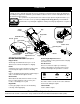
ASSEMBLY NOTE: Reference to right and left hand side of the Yard Vacuum is observed from the operating position. See Figure 1. This Yard Vacuum has been completely assembled at the factory, except for the handle, bag, and blower chute. These parts are shipped loose in the carton. A pair of safety glasses and a 20-oz. bottle of engine oil are also included in the carton. See Figure 1. 20-oz.
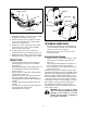
• • • • Secure the two handles by tightening the upper wing nuts (carriage bolts must be seated properly into the handle). Remove the hairpin clips from the handle brackets and remove the carriage bolts and wing nuts from the lower handle. See Figure 3. Place the bottom holes in lower handle over the pins on handle brackets and secure with hairpin clips. Insert carriage bolts through upper hole in lower handle from the outside and secure with wing nuts.
• Raise the nozzle height to the highest setting when using the blower chute. Refer to nozzle height adjustment in the ADJUSTMENT section. NOTE: The bag/chute switch button attached to the mounting bracket must be fully depressed by the tip of front tab on the blower chute or engine will not start.
OPERATION Know Your Yard Vacuum Read this operator’s manual and safety rules before operating your Yard Vacuum. Compare the illustrations below with your equipment to familiarize yourself with the location of various controls and adjustments. Save this manual for future reference. The operation of any Yard Vacuum can result in foreign objects being thrown into the eyes, WEAR YOUR SAFETY GLASSES which can result in severe eye damage.
Hose Assembly • Used as an alternative to the nozzle to vacuum yard waste such as leaves or pine needles in hard to reach places. Hose Handle Used to guide hose assembly when vacuuming. • Nozzle/Hose Vac Handle The nozzle/hose vac handle is located on top of the nozzle and it is used to regulate the vacuum between the nozzle and the hose assembly. WARNING: Use extreme care when handling gasoline. Gasoline is extremely flammable and the vapors are explosive.
Throttle Control Buttons Inner Flap Bag Clip Bag Handle Outer Flap Choke Control Strap Figure 8 7. Standing behind the unit, grasp starter handle and pull rope out until you feel a drag. 8. Pull the rope with a rapid, continuous, full arm stroke. Keep a firm grip on the starter handle. Let the rope rewind slowly. Figure 9 TO REMOVE BLOWER CHUTE 9. Repeat, if necessary, until engine starts. When engine starts, move choke control gradually away from the throttle control.
Nozzle Height Adjustment Nozzle/Hose Vac Handle (Top Position) The nozzle can be adjusted to any six positions, ranging from 5/8” to 4 1/8” ground clearance. The nozzle height has to be adjusted according to the conditions. Move the height adjustment levers forward or backward to adjust the nozzle upwards or downwards. See Figure 12. NOTE: In general, raise the nozzle height to vacuum a thick layer of leaves or to operate with the blower chute and lower the nozzle height for smoother surfaces.
PRODUCT MAINTENANCE SCHEDULE Be for ee ac hu se Af te r ea ch us e Fir st 5h ou rs Ev er y2 5h ou rs Ev er y5 0h ou rs Be fo r es to r ag e MAINTENANCE Lubrication Clean equipment ENGINE Check engine oil Change engine oil Service air cleaner Service spark plug Service muffler Clean engine GENERAL RECOMMENDATIONS CLEAN EQUIPMENT • • • • • • Always observe safety rules when performing any maintenance.
TO DRAIN OIL SERVICE SPARK PLUG Drain oil while engine is warm. Follow the instructions given below. • • • • • • Drain the gas tank, start the engine and let it run until the fuel line and carburetor are empty. Remove oil fill dipstick. Tip unit on its side to drain through the oil fill tube. When engine is drained of all oil, refill with approximately 20 oz. of fresh oil. Refer to Gas And Oil Fill-up in OPERATION section. Replace dipstick. Clean the spark plug and reset the gap to .
SERVICE AND ADJUSTMENTS WARNING: Do not at any time make any adjustment to the unit without first stopping engine and disconnecting spark plug wire. WARNING: Do not attempt to alter the engine speed by tampering with the engine’s governor linkage. Doing so could result in serious personal injury and damage to the engine. The engine RPM has been set at the factory. Nozzle Height Adjustment The nozzle can be adjusted to any six positions, ranging from 5/8” to 4 1/8” ground clearance.
SHARPENING OR REPLACING CHIPPER BLADE • Because the engine on this unit has a tapered crankshaft, a special impeller removal tool (part number 753-0900) is required to remove the impeller assembly. For further assistance, contact your Sears Service Center. • NOTE: When tipping the unit, empty the fuel tank and keep engine spark plug side up. Chipper Blade • • • Remove lock nut that secures flail screen to the lower housing. The flail screen does not have to be removed. Refer to Figure 15.
STORAGE NOTE: Fuel stabilizer is an acceptable alternative in minimizing the formation of fuel gum deposits during storage. Prepare your Craftsman Yard Vacuum for storage at the end of the season or if the unit will not be used for 30 days or longer. A yearly check-up by your local Sears Service Center is a good way to ensure that the unit runs properly next season. • Add stabilizer to gasoline in fuel tank or storage container. • Always follow the mix ratio found on stabilizer container.
TROUBLESHOOTING Problem Possible Cause(s) Corrective Action Engine fails to start 1. Fuel tank empty or stale fuel. 1. Fill tank with clean, fresh gasoline. Fuel will not last over thirty days unless a fuel stabilizer is added. 2. Connect wire to spark plug. 3. Obstruction lodged in impeller. Disconnect spark plug wire and remove lodged object. 4. Move CHOKE to ON position. 5. Clean, adjust gap or replace. 6. Safety switch must be depressed by the front tab on the bag handle when securing the bag. 7.
PARTS LIST Sears Craftsman 6.0 H.P. Yard Vacuum Model 247.
Sears Craftsman 6.0 H.P. Yard Vacuum Model 247.770550 Ref. No. 1. 2. 3. 4. 5. 6. 7. 8. 9. 11. 12. 13. 14. 15. 16. 17. 18. 19. 20. 21. 22. 23. 24. 25. 26. 27. 28. 29. Part No. 736-0451 749-0438D 720-0279 712-3004A 710-1205 781-1056 710-0528 720-0241 710-1174 710-0604A 681-0174 749-0907B 711-1293 710-0703 712-0397 751B282454 725-1700 725-3166 731-1613 710-0224 629-0920 714-0104 736-0264 732-0962 781-0778A 747-1153 710-3195 710-3025 Ref. No. Part Description 30. 31. 32. 33. 34. 35. 36. 37. 38. 39. 40. 41.
Sears Craftsman 6.0 H.P. Yard Vacuum Model 247.
Sears Craftsman 6.0 H.P. Yard Vacuum Model 247.770550 Ref. No. Part No. 1. 2. 3. 4. 5. 6. 7. 8. 9. 10. 11. 12. 664-0094 681-0154 710-1054 781-0490 719-0530A 781-0735 719-0329 715-0166 711-1401 712-0411 736-0119 681-0152 13. 14. 15. 16. 17. 18. 19. 20. 21. 22. 23. 24. 25. 26. 27. 28. 29. 30. 31. 32. 710-1238 781-0721A 712-3004A 712-3027 736-0142 714-0225 711-1560 731-2294 781-1064 732-1156 726-0106 711-1551 712-0161 736-0400 731-2485 710-1156 750-1294 732-3118 732-1151 732-1150 Ref. No.
CONTENIDO Contenido Página Contenido Página Garantía 22 Servicio y ajustes 34 Seguridad 23 Almacenamiento 36 Montaje 25 Localización de averías 37 Operación 28 Lista de repuestos 18 Mantenimiento 32 GARANTIA Garantía de un año sobre la aspiradora para jardines Craftsman Por un período de un año a partir de la fecha de compra, Sears reparará gratis cualquier defecto en el material o fabricación de esta aspiradora para jardines Craftsman, siempre y cuando haya sido mantenida, lubricada y
SEGURIDAD ADVERTENCIA: Este símbolo indica instrucciones de seguridad muy importantes las que, si no se siguen, podrían poner en peligro la seguridad personal y/o causar daños físicos. Antes de intentar manejar esta aspiradora para jardines, se debe leer y seguir todas las instrucciones que aparecen en este manual. Si no se cumplen estas instrucciones se corre el riesgo de sufrir lesiones. Cuando en el manual aparece este símbolo, respetar su advertencia.
• • • • • • • • SERVICIO piedras, pedazos de vidrio o de metal) y sean lanzados por la boca de descarga. Al elevar la boquilla a la posición más alta también incrementa la admisión de aire para lograr mejor funcionamiento del soplador. No intentar nunca retirar o vaciar el recolector mientras el motor está funcionando. Apagar el motor y esperar hasta que el rotor esté detenido antes de retirar el recolector (bolsa). El rotor continúa girando por algunos segundos después de apagar el motor.
MONTAJE NOTE: Para determinar los lados derecho e izquierdo de la aspiradora para jardines, situarse detrás de la máquina, en posición de manejarla. Ver la figura 1. Botella de 20 oz. aceite para motor La aspiradora para jardines fue armada en la fábrica, con la excepción del manillar, recolector y tubo de soplado. Estos componentes se envían sueltos en la caja de cartón. En la caja también se incluyen anteojos de seguridad y una botella de 20 onzas de aceite para motor. Ver la figura 1.
• • Retirar las chavetas de las escuadras del manillar y los tornillos de carruaje (cabeza de hongo y cuello cuadrado) y tuercas de mariposa del manillar inferior. Ver la figura 3. Colocar el manillar inferior sobre los pasadores en las escuadras y fijarlos con las chavetas, tornillos de carruaje y tuercas de mariposa.
• • • Asir el tubo de soplado con una mano y, con la otra mano, tirar de la varilla de fijación en la escuadra de montaje hacia el motor. Use el final de soporte de montaje como el apalancamiento deslizando la barra que se cierra. Ver la Figura 6. Deslizar el tubo de soplado por encima del borde de la boca de descarga y soltar la varilla de fijación para sujetar el tubo en su lugar. Cuando se va a usar el tubo de soplado, elevar la boquilla a la posición más alta.
OPERACION Conozca su aspiradora para jardines Lea este manual del operador y las reglas de seguridad antes de manejar su aspiradora para jardines. Compare las ilustraciones presentadas más abajo con su equipo para que conozca bien la ubicación de los distintos controles y ajustes. Guarde este manual para consultarlo en el futuro. USE SUS El manejo de cualquier aspiradora para jardines sopladora puede causar el lanzamiento de ANTEOJOS DE objetos extraños contra los ojos y lesionarlos gravemente.
Montaje de la manguera Se usa como alternativa del uso del pico para aspirar los desechos que se acumulan en los patios como por ejemplo las hojas o las agujas de los pinos que se encuentran en lugares de difícil acceso. • Manija de la manguera Se utiliza para guiar el montaje de la manguera mientras se aspira.
• Desconectar el cable de la bujía y conectarlo a tierra en el pilar retenedor para impedir el arranque accidental mientras la máquina está sola. la estrangulación gradualmente a la posición de START/run. 10. Si el motor vacila, mueva la palanca de mando a la posición de la ESTRANGULACIÓn, entonces de nuevo a la posición de START/run. ADVERTENCIA: Al mover la palanca de mando de válvula reguladora, tenga cuidado de superficies calentadas y de bordes sostenidos del silenciador guarde. 11.
• Uso del montaje de la manguera hacia el motor con la otra mano para soltarlo. Consulte Figura 6. Saque el canal de soplado del borde de la abertura de descarga. • Uso del pico de la aspiradora • • Coloque la manija del pico / manguera de la aspiradora en la posición superior del pico para aspirar a través del mismo. Ver Figura 10. • El perno con resorte debe estar en el primer agujero de la adaptación de la manguera para operar el pico de la misma.
PRODUCTO PROGRAMA DE MANTENIMIENTO An te alm s d ac el en am De ien sp to ca ué da s d us e o Pr im er as 5h or Ca as da 25 ho ra s Ca da 50 ho ra s An te s na d mi el en alm to a ce - MANTENIMIENTO Lubricación Limpiar el equipo Revisar nivel aceite MOTOR Campiar aceite motor Limpiar filtro de aire Limpiar la bujía Limpiar el silenciador Limpiar el motor RECOMENDACIONES GENERALES LIMPIEZA DEL EQUIPO • • • • • • Siempre respetar las reglas de seguridad durante los trabajos de mantenimiento.
PARA VACIAR EL ACEITE SERVICIO DE LA BUJIA Vaciar el aceite mientras el motor está caliente. Seguir las instrucciones siguientes. • • • • • • Vaciar el tanque de gasolina, arrancar el motor y dejarlo funcionando hasta que la tubería de combustible y el carburador estén vacíos. Retirar la varilla de medición de llenado de aceite. Inclinar la máquina sobre su costado para vaciar el aceite por el tubo de llenado.
SERVICIO Y AJUSTES máquina a un centro de servicio Sears para reparación y ajuste. ADVERTENCIA: Nunca hacer ningún ajuste a la máquina sin primero apagar el motor y desconectar el cable de la bujía. WARNING: No intentar alterar la velocidad del motor moviendo el varillaje del gobernador del motor. El hacerlo podría resultar en graves lesiones personales y daño al motor. La velocidad (rpm) del motor fue ajustada en la fábrica.
• • Retirar el tornillo hexagonal y la arandela plana ubicados encima de la carcasa trasera cerca de la escuadra de montaje y la contratuerca que sujeta la rejilla de flagelos. Ver las Figura 14. Retirar y limpiar la rejilla con una rasqueta o lavarla con agua. Volver a instalar la rejilla. Caja Tornillos AFILADO O REEMPLAZO DE LA CUCHILLA ASTILLADORA Debido a que el motor de esta máquina tiene el cigüeñal cónico, se necesita un extractor especial (número de pieza 753-0900) para retirar el impulsor.
• Apretar los tornillos de la cuchilla a 210 - 250 pulg-lbs. • Apretar el perno del rotor a 375-425 pulg-lbs. NOTE: Asegurar de instalar la cuchilla astilladora con el filo hacia arriba. Ver la Figura 19. Cuchilla astilladora Cuchilla de flagelos Rotor Figura 19 ALMACENAMIENTO Preparar la aspiradora para jardines Crafstman para su almacenamiento al final de la temporada o si la máquina va a estar sin usar durante 30 días o más.
LOCALIZACION DE AVERIAS Problema Causas posibles Solución El motor no arranca 1. El tanque de combustible está vacío o combustible está viejo. 1. Llenar el tanque con gasolina limpia y fresca. El combustible no durará más de treinta días a menos que se le añada un estabilizador. 2. Conectar el cable de la bujía. 2. El cable de la bujía está desconectado. 3. No se puede tirar de la cuerda de arranque. 4. El estrangulador está en la posición ON (conectado). 5. La bujía está mala. 6.