
Operator`s manual

WARNING: Do not at any time make any
adjustments without first stopping
engine, disconnecting spark plug wire,
and grounding it against the engine.
Always wear safety glasses during
operation or while performing any
adjustments or repairs.
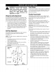
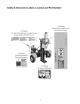
WedgeAssemblyAdjustment
AS normal wear occurs and there is excessive _'play"
between the wedge and beam, adjust the bolts on the
side of the wedge assembly to eliminate the excess
space between the wedge and beam. See Figure 10.
Loosen the jam nuts on the two adjustment bolts
on the side of the wedge. Turn the adjustment
bolts in until snug and then back them off slowly
until the wedge assembly will slide on the beam.
Tighten the jam nuts securely against the side of
the wedge to hold the adjustment bolts in this
position.
GibPlateAdjustment
Periodically remove and replace the "gibs" (spacers)
between the wedge plate and the back plate.
See Figure 10.
NOTE: The gibs may be rotated and/or turned over
for ever wear.
Loosen the lock nuts under the each back plate
and slide the gibs out.
Turn or replace the gibs.
Reassemble the back plate and secure with the
lock washers and lock nuts.
Readjust the bolts on the side of the wedge
assembly.
Adjustment
Bolts
\
\ i
\
\
\
I
/ i
/// i
/ I
I
Nex Jam Ntlt
I
Lock
Washer
Figure 10
HoseClamps
Check the hose clamps on the suction hose (attached
to side of the pump) for proper tightness before each
use. Check the hose clamps on the return hose at
least once a season.
FlexiblePumpCoupler
The flexible pump coupler is a nylon "spider" insert,
located between the pump and engine shaft. Over a
period of time, the coupler will harden and
deteriorate.
Replacement is needed if you detect vibration or
noise coming from the area between the engine and
the pump. If the coupler fails completely, you will
experience a loss of power.
IMPORTANT: Never hit the engine shaft in any
manner, as a blow will cause pemlanent damage to
the engine.
When replacing the flexible pump coupler, proceed
as follows:
Remove three nuts and lock washers that secure
the pump to the coupling shield. Two nuts are at
the bottom corners and one is in the top center.
Remove the pump.
Rotate the engine by slowly pulling starter handle
until engine coupling half set screw is visible.
Loosen set screw using allen wrench and slide
coupling half off of engine shaft.
Loosen set screw on pump coupling half and
remove coupling half.
Slide new engine coupling half onto the engine
shaft until the end of the shaft is flush with the
inner portion of the coupling half. (There must be
space between end of the engine support bracket
and coupling half). Tighten set screw.
Install pump coupling half and key on pump shaft.
Rotate coupling half until set screw faces opening
in shield. Do not tighten set screw.
Install nylon "spider" onto engine coupNng half.
Align pump coupling half with nylon "spider" by
rotating engine using starter handle. Slide
coupNng half into place while guiding three
mounting bolts through holes in pump support
bracket.
Secure with nuts and washers removed earlier.
12