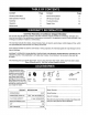
Owner's Manual CRAFTSMAN 8.0 Horse Power 3" diameter chipping capacity CHIPPER-SHREDDER Model No. 247.775860 CAUTION" Before using this product, read this manual and follow all Safety Rules and Operating Instructions. Sears, Roebuck and Co., Hoffman Printed in U.S.A. Estates, IL 60179, U.S.A.
Content Page Content Page Warranty Information 2 Service & Adjustment 14 Safe Operation Practices 3 Off-Season Storage 17 Assembly 5 Trouble-Shooting 18 Operation 8 Repair Parts 19 Maintenance 11 One-Year Warranty on Craftsman Chipper-Shredder For one year from the date of purchase, when this Craftsman chipper-shredder is maintained, lubricated, and tuned up according to the operating and maintenance instructions in the operator's manual, Sears will repair, free of charge, any defect
This symbol points out important safety instructions which, if not followed, could endanger the personal safety and/or property of yourself and others. Read and follow all instructionsin this manual before attempting to operate your chipper shredder. Failure to comply with these instructionsmay result in personal injury.When you see this symbol--heed its warning. Your chipper-shredder was built to be operated according to the rules for safe operation in DANGER: ,_ this manual.
impeller to come to a complete stop. The impeller continues to rotate for a few seconds after the engine is shut off. Never place any part of the body in the impeller area until you are sure the impeller has stopped rotating. Muffler and engine become hot and can cause a burn. Do not touch. e b. Replace gasoline cap securely and wipe off any spilled gasoline before starting the engine as it may cause a fire or explosion. c. Extinguish all cigarettes, cigars, pipes and other sources of ignition. d.
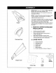
IMPORTANT: This unit is shipped without gasoline or oil in the engine. After assembly, see OPERATION section of this manual for proper fuel and engine oil fill-up. \ \ NOTE: To determine right and left hand sides of your chipper-shredder, stand behind the unit with the engine farthest away from you. \ Your chipper-shredder has been completely assembled at the factory, except for the hopper assembly, chipper chute, discharge chute and the catcher bag. These parts are shipped loose in the carton.
3. TOOLS REQUIRED 1. 2. 3. Place second spacer over hex bolt inside the other part of the hinge. Secure with hex lock nut. Tighten securely. Secure both sides of discharge chute to housing using wing knobs that you earlier removed. Tighten wing knobs. 1/2" or Adjustable Wrenches 7/16" or Adjustable Wrenches Funnel 4. DISCONNECTING SPARK PLUG 6. A'n'ACHING Disconnect the spark plug wire and move it away from the spark plug before assembling the chipper-shredder. See figure 2.
t o Q Tighten the bolt. This will secure the hopper assembly to the inlet guide. To raise the hopper, hold the hopper by the hand-hold and lift it up till it clicks into position. To Iowerthe hopper, hold the hopper by the hand-hold and pull the release bar. The hopper should drop down. See figure 5. Remove the two sets of hex bolt, lock nut, and flat washer from the two holes on the upper end of the brace. 1. Lift hopper up , / o o 2. Pull release bar Q ® Figure 5 7.
Read this owner's manual and safety rules before operating your chipper-shredder. Compare the illustrations with your chipper-shredder to familiarize yourself with the location of various controls and adjustments. Save this manual for future reference. The operation of any chipper-shredder can result in foreign objects being thrown into the eyes, which can result in severe eye damage.
Stopping Engine Move throttle control lever to STOP position. Disconnect spark plug wire and move away from spark plug to prevent accidental starting. o WARNING: Before using your chippershredder, again refer to the safety rules on page 3 and 4 of this manual. Always be careful. Oil (Packed with unit) Only use high quality detergent oil rated with API service classification SF, SG or SH. Select the oil's viscosity grade according to your expected operating temperature. Follow the chart below.
4. STARTING WARNING: ENGINE NOTE: A noise will be heard when finding the start of the compression cycle. This noise is caused by the flails and fingers which are part of the shredding mechanism falling into place, and should be expected. In addition, the flails and fingers will be noisy after the engine is started, until the impeller reaches full speed. Be sure no one other than the operator is standing near the chippershredder while starting or operating.
is likelythattheshreddingbladeand/orchipper bladesaredullandneedtobesharpened or replaced.RefertoServiceandAdjustments section. IMPORTANT: Thereisa flailscreenlocatedinside thehousinginthedischarge area.Iftheflailscreen becomesclogged,removeandcleanas instructed in theServiceandAdjustments section. WARNING:Thechipper-shredder discharges materials withconsiderable velocity.Keepaway from the area around the discharge chute.
CUSTOMER MAINTENANCE _ _" RESPONSIBILITIES _ p p _o" SERVICE DATES S Oil pivot points g o. Clean shredder Check engine oil u.I Z m Change engine oil Service air cleaner Z ILl Clean engine Reset spark plug Clean muffler checking oil level. With engine on level ground, the oil must be to FULL mark on dipstick. Change engine oil after the first five hours of operation, and every twenty-five hours thereafter. 2.
theenginewithoutaircleanercompletely assembled. ToServiceAir Cleaner: 1. 2. 3. • Service pre-cleaner after every 25 hours of use, or at least once a season. Service filter every 100 hours of use, or at least once a season. Service pre-cleaner and filter more often under dusty conditions. Remove wing nut and cover. Slide pre-cleaner off filter. Clean the inside of base and cover thoroughly.
4. LUBRICATION Muffler WARNING: Do not operate the chippershredder without a muffler, or tamper with the exhaust system. Damaged mufflers or spark arresters could create a fire hazard. Lubricate the pivot points on the release bar, hopper assembly, chute deflector and chipper chute once a season using a light oil. See figure 16 Inspect periodically, and replace if necessary. If your engine is equipped with a spark arrester screen assembly, remove every 50 hours for cleaning and inspection.
2. SHARPENING OR REPLACING THE BLADES Shredding Blade The shredding blade may be removed for sharpening or replacement as follows. • Disconnect spark plug wire and move it away from spark plug. • Lower the hopper assembly. Block up the housing. See figure 19. Chipper Blades Disconnect spark plug wire and move it away from spark plug. Remove the flail screen as instructed in previous section. Using a 1/2" wrench, remove the chipper chute by removing three hex nuts and washers. See figure 17.
equalamountofgrindingto preventan unbalanced blade. Anunbalanced bladewillcauseexcessive vibrationwhenrotatingathighspeedsandmay causedamage totheunit.Thebladecanbetested forbalance bybalancing itona roundshaft screwdriver ornail.Removemetalfromtheheavy sideuntilitisbalanced evenly. Seefigure20. Whenreassembling theblade,tightencenter bolttobetween550and650inch-pounds and thetwoouterboltstobetween250and350inchpounds,or lackingtorquewrench,tighten securely. 1. Insert screw driver through hole d./ 2.
WARNING:Neverstoremachinewithfuel inthefueltankinsideofbuildingwhere fumesmayreachan open flame or spark, carburetor. Do not drain the gas tank and carburetor if using fuel stabilizer. Drain all the oil from the crankcase (this should be done after the engine has been operated and is still warm) and refill the crankcase with fresh oil. If you have drained the fuel tank, protect the inside of the engine as follows.
PROBLEM Engine fails to start POSSIBLE 1. 2. 3. 4. CAUSE Fuel tank empty, or stale fuel Spark plug wire disconnected Faulty spark plug Throttle control not in correct position Loss of power; operation erratic 1. Spark plug wire loose 2. Unit running on Choke 3. Blocked fuel line or stale fuel 4. Water or dirt in fuel system 5. Carburetor out of adjustment 6. Dirty air cleaner Engine overheats 1. Carburetor not adjusted properly 2. Engine oil level low CORRECTIVE 1. 2. 3. 4.
SEARS CRAFTSMAN 8 H.P. CHIPPER=SHREDDER MODEL 247.775860 16 79 76 8 _o _ .
SEARS CRAFTSMAN KEY NO. 8 H.P. CHIPPER-SHREDDER KEY NO. DESCRIPTION PART NO. MODEL 247.775860 PART NO. DESCRIPTION 770-0549M Owner's Manual 39 710-3008 Hex Bolt 5/16-18 x .75" (Gr. 5) 1. 742-0571 Shredder Blade 4O 710-0442 Hex Bolt 5/16-18 x 1.5" 2. 710-1254 Hex Patch Bolt 3/8-24 x 2.25" Lg. (Gr.8) 41 681-0004A Flail Housing Ass'y. -- Outer 42 681-0117 Flail Housing Ass'y. -- Inner 3 143,978005 Engine 43 710-0106 Hex Scr. 1/4-20 x .
SEARS CRAFTSMAN 8 H.P. CHIPPER-SHREDDER MODEL 247.775860 Table continued from page 20) KEY NO. DESCRIPTION PART NO. 77 781-0492A Hopper -- Pivot Door 79 726-0106 Cap Speed Nut 1/4" Rod 8O 781-0692 Upper Hopper 81 781-0693 Lower Hopper 82 712-0107 Lock Nut 1/4"- 20 83 781-0698 Hopper Lockout Bracket 84 749-1004 Chipper Chute Support 85 781-0633 Flap Strip 86 710-0286 Screw 1/4"- 20.5in.
SEARS CRAFTSMAN 8 H.P. ENGINE MODEL 143.978005 CHIPPER-SHREDDER FOR MODEL 247.775860 ooo] t 80 83 81 _i__'_ 292 75 71 342 87 89 70 69 101 47 • 171 169, / 25 26 162 / 184, -1 \ 277 276 277A 240 / 245 245A 3700_.[_]-" 250 / 251 416 22 325 _..
SEARS CRAFTSMAN CHIPPER-SHREDDER Key No. 1 2 4 5 15 15A 15B 16 17 18 19 20 25 26 28 30 35 36 37 38 40 41 42 43 45 47 48 49 5O 60 65 69 70 71 72 75 8O 81 82 83 84 86 87 89 90 Part No. 35385 27652 30969 30699C 30700 650494 33454 29916 651028 34663 35319 36460 650561 30322 36283A 29826 29918 29216 29642 34552 34553 34554 34329A 34330A 34331A 34332 34333 34334 27888 36897 651033 34034 36896 35375 33273A 650128 35262A 35376 35377 28582 35319 31845 30590A 35378 30588A 29193 650833 650832 32589 611O90 8 H.
SEARS CRAFTSMAN CHIPPER-SHREDDER 8 H.P. ENGINE MODEL 143.978005 FOR MODEL 247.775860 Key No. Part No. Description Key No. Part No.
SEARS CRAFTSMAN CHIPPER-SHREDDER 8 H.P. ENGINE MODEL 143.978005 FOR MODEL 247.775860 Carburetor Key No. 20 Part No. Description 632351 Carburetor (Incl.
SEARS CRAFTSMAN 8 H.P. ENGINE MODEL 143.978005 CHIPPER-SHREDDER FOR MODEL 247.775860 -11 // 13 Key No. Part No. Description 1 2 3 4 5 6 7 8 11 12 13 59O704 590599A 590600 590696 590601 59O697 590698 590699 590700 590705 590535 590701 Recoil Starter Spring Pin (Incl. 4) Washer Retainer Washer 12 8 q_--2 26 Brake Spring Starter Dog Dog Spring Pulley & Rewind Spring Ass'y Starter Housing Ass'y Starter Rope (98" x 9/64" Dia.
:orthe repairor replacementpartsyou need delivereddirectlyto yourhome Call7 am - 7 pm, 7 days a week 1-800-366 PART (1-800-366-7278) Forin-homemajor.
Manual del Propietario CRRFTSMRN 8.0 HP Capacidad de astillado de 3" de dia.metro ASTILLADORA-DESMENUZADORA Modelo No. 247.775860 PRECAUClON: Antes de operar este equipo lea y observe todas las reglas e instrucciones de seguridad Sears, Roebuck Impreso en U.S.A. and Co., Hoffman Estates, IL 60179, U.S.A.
Contenido P#,gina Informaci6n de garantfa 2 Pr_.
& & Este simbolo indica instrucciones importantes de seguridad las cuales, si no se observan, pueden poner en peligro la seguridad personal y/o la propiedad suya y de otras personas. Lea y observe todas las instrucciones de este manual antes de intentar operar su astilladora-desmenuzadora a gasolina. La falla en cumplir con estas instrucciones puede resultar en lesiones personales -- obedezca la advertencia.
• Nuncatratederetirarnivaciarlabolsacolectora cuando elmotorestAfuncionando. Apague elmotoryespere hastaquelahelicesedetenga completamente. Lah_licecontint_a girando durante unossegundos despu6s deapagar elmotor. Nunca coloque ninguna partedesucuerpo enel Areadelahelicehastaqueesteseguroquelaheliceha detenido sugiro. • Elsilenciador y el motorsecalientan y pueden causar quemaduras. Nolostoque. • Nopermita quehojasuotrosdesechos seacumulen sobreel silenciador delmotor.
IMPORTANTE: Esta unidad se despacha sin gasolina ni aceite en el motor. Vea la secci6n de OPERACION de este manual para las recomendaciones sobre combustible y aceite de motor adecuados, despues del ensamblado. NOTA: Para determinar los lados izquierdo y derecho de su astilladora-desmenuzadora, parese detras de la unidad con el motor en posiciSn mas alejado de usted.
3. HERRAMIENTAS REQUERIDAS 1. Llaves de 1/2" o ajustables 2. Llaves de 7/16" o ajustables 3. Embudo 4. DESCONEXlON • • • DE LA BUJIA Desconecte el cable de la bujfa y mu_valo alejado de la bujfa antes de ensamblar la astilladora-desmenuzadora. Vea la figura 2. Cable de la bujia 6. FIJAClON DEL CONJUNTO LA TOLVA • • • • • Figura 2 • 5. FIJACION DE LA CANALETA DESCARGA DE Coloque la segunda arandela sobre el perno hexagonal dentro de la otra mitad de la bisagra.
o Ajuste el perno. Esto asegurar_, el conjunto de la tolva a la gufa de entrada. Para elevar la tolva, sujetela por el mango y lev_ntela hasta que calce en posici6n. Vea la figura 5. Para bajar la tolva, suj6tela por el mango y tire de la barra de desenganche. La tolva deberfa descender. Vea la figura 5. Eleve la tolva • Extraiga los dos juegos de pernos hexagonales, tuerca de seguridad y arandela plana, de los dos orificios en el extremo superior del estribo.
Antes de operar su astilladora-desmenuzadora ustraciones con su astilladora-desmenuzadora Guarde este manual para referencia futura. lea este manual del propietario y las reglas de seguridad. Compare las il- I para familiarizarse con la ubicaci6n de los varios controles y ajustes.! La operaci6n de una astilladora-desmenuzadora puede resultar en que objetos extraSos sean despedidos contra los ojos, J Io que puede lesionarlos gravemente.
Detencibn del motor Mueva la palanca de control del acelerador a la posici6n STOP. Desconecte el cable de la bujia y alejelo de la bujfa para prevenir un arranque accidental. reglas de seguridad en las pdginas 3 y 4 de este ADVERTENCIA: nuevamente a las manual, antes deRefierase usar esta astilladora-desmenuzadora. Tenga siempre cuidado. _ 3.
4. ARRANQUE DEL MOTOR NOTA: AI comienzo del ciclo de compresi6n se escuchar_ un ruido. Este ruido est_ causado por las desgranadoras y dedos que forman parte del mecanismo desmenuzador calzando en su lugar, y debe esperarse. Adem_s, las desgranadoras y dedos har_n ruido despu6s de arrancarse el motor, hasta que la h_lice alcance m_xima velocidad. na ademds del operador est_ parada cerca de la ADVERTENClA: AsegL_resealque ningunau operar.
descarga elmaterial, esposible quelacuchilla desmenuzadoray/olascuchillas astilladoras est_ndesafiladas yrequieranafilarseo reemplazarse. Refierase a la secci6nde Servicio yAjustes. ADVERTENClA: La astilladora-desmenuzadora descarga materiales con considerable velocidad. Mantdngase alejado del _rea alrededor de la canaleta de descarga. AI extraer o fijar la bolsa, cambiar bolsas o extraer el material desmenuzado, detenga siempre el motor y desconecte el cable de la bujfa.
MANTENIMIENTO @ I O O f Aceitar los puntos de pivote FECHAS DE SERVICIO _/ a O Limpiar la desmenuzadora */ _/ n Inspeccionar el aceite del motor _/ Cambiar el aceite del motor 0 _J _/ Limpiar el filtro de aire _/ Limpiar el motor _/ Reajustar la bujia _J Limpiar el silenciador _/ 4 _/INSPECCIONAR 2. LIMPIEZA • • Para drenar el aceite: • Drene el aceite mientras el motor est,. caliente. Siga las instrucciones de abajo. • Saque la tapa de drenaje de aceite.
l Para prestar servicio al filtro de aire 1. Preste servicio al prefiltro despues de cada 25 horas de uso, o por Io menos una vez por temporada. 2. Preste servicio filtro cada 100 horas de uso, o por Io menos una vez por temporada. 3. Preste servicio al prefiltro y al filtro m_s frecuentemente bajo condiciones polvorientas. • Extraiga la tuerca mariposa y la cubierta. Vea el recuadro de la figura 13, para la ubicaci6n. Aleta de enfriamiento Figura 14 .
4. LUBRICACION Silenciador _i menuzadora sin un silenciador ni manipule el ADVERTENClA: No Los opere la astilladora-dessistema de escape. silenciadores o supresores de chispas dafiados pueden crear un riesgo de incendio. Lubrique los puntos pivote en la barra de desenganche, conjunto de la toIva, deflector de la canaleta y canaleta de la astilladora, una vez por temporada usando un aceite liviano. Vea la figura 16. Inspeccione peribdicamente y reempl_celo si fuera necesario. Si su motor est,.
2. AFILADO O REEMPLAZO CUCHILLAS Cuchilla de la desmenuzadora La cuchilla de la desmenuzadora puede extraerse para afilar o reemplazar segL_nIo siguiente: • Desconecte el cable de la bujia y muevalo alejado de la bujia. • Baje el cenjunto de la telva. Bloquee el armaz6n. Vea la figura 19. DE LAS Cuchillas de la astilladora • Desconecte el cable de la bujfa y muevalo alejado de la bujfa. • Extraiga el tamiz de la desgranadera segt_n se instruye en la secci6n previa.
• Unacuchilla desequilibrada causara unavibraci6n excesivaalgirara altasvelocidades y puede causardafiosa la unidad,la cuchilla puedeprobarse porequilibrio equilibr_ndola sobreundestornillador dehojaredonda osobre unclavo.Desgaste el metaldelladomaspesado hasta quela unidadest6uniformemente equilibrada. Yeala Figura 20.
_ NOTA: El estabilizador de combustible es una alternativa aceptable para miniminizar la formaciSn de dep6sitos de goma del combustible durante el almacenamiento. • Agregue el estabilizador a la gasolina en el tanque de combustible o recipiente de almacenamiento. • Siempre siga la proporci6n de mezcla de combustible indicada en el recipiente del estabilizador. • Despu_s de agregar estabilizador haga funcionar el motor durante 10 minutos por Io menos, para permitir que el estabilizador Ilegue el carburador.
PROBLEMA CAUSA POSIBLE ACCION CORRECTORA El motor no arranca 1. Tanque de combustible vacfo, o combustible rancio. 2. Est_ desconectado el cable de la bujfa. 3. Bujfa defectuosa. 4. El control del acelerador no estA en la posici6n correcta. 1. Llene el tanque con combustible limpio y fresco. 2. Conecte el cable a la bujfa. 3. Limpie, ajuste la separaci6n o reemplace. 4. Mueva el control del acelerador a la posici6r FAST. Perdida de potencia, funcionamiento err_.tico 1.
F Sears se complace en ofrecer a sus clientes servicio de reparaci6n de aparatos electrodom_sticos y electrbnicos de todas las marcas. En Sears, usted puede contar con operadores en espa_ol, a los que puede Ilamar sin cargo alguno.