OWNER'S MANUAL MODELNO. 247.795940 I:RRFTSMRN® Caution: Readand Follow All SafetyRules andInstructions BeforeOperating This Equipment 5 HORSEPOWER 3 CUTTING STAGE MULCHING AND BAGGING CHIPPER-SHREDDER Assembly Operation Customer Responsibilities Service and Adjustment Repair Parts I ii ii SEARS,ROEBUCKAND CO., HoffmanEstates, IL 60179 U.S.A. Printed in U.S.A.
SAFETY RULES I_ WARNING: TO REDUCE SAFETY INSTRUCTIONS, PERSONAL INJURY. THE POTENTIAL FOR ANY INJURY, FAILURE TO COMPLY WITH THE TRAINING • Read this owner's manual carefully in its entirety before attempting to assemble or operate this machine. Be completely familiar with the controls and the proper use of this machine before operating it Keep this manuat in a safe place for future and regular reference and for ordering replacement parts. • Children must never be allowed to operate this equipment.
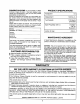
CONGRATULATIONS PRODUCT SPECIFICATIONS on your purchase of a Sears Craftsman Chipper-Shredder. It has been designed, engineered and manufactured to give you the best possible dependability and performance. Should you experience any problem you cannot easily reinedy, please contact your nearest Sears Service Center/ Department in the United States. We have competent, welltrained technicians and the proper tools to service or repair this unit. Please read and retain this manual.
TABLE OF CONTENTS SAFETY RULES ......................................................... 2 PRODUCT SPECIFICATIONS ................................... 3 MAINTENANCE AGREEMENT .................................. 3 CUSTOMER RESPONSIBILITIES ............................. 3 WARRANTY ............................................................... 3 INDEX ......................................................................... 4 ASSEMBLY ................................................................
iiii ASSEMBLY INSTRUCTIONS IMPORTANT: This unit is shipped WITHOUT GASOLINE or OIL. After assembly, see operation section of this manual for proper fuel and engine oil recommendations. NOTE: To determine right and left hand sides of your chipper-shredder, stand behind and face the hopper (engine is at the front of the unit). Your chipper-shredder has been completely assembled at the factory, except for the chute deflector and the catcher bag. A pair of safety glasses are atso included in the carton.
OPERATION KNOW YOUR CHIPPER-SHREDDER READ THIS OWNER'S MANUAL AND SAFETY RULES BEFORE OPERATING YOUR CHIPPER-SHREDDER. Compare the illustrations with your chipper-shredder to familiarize yourself with the location of various controls and adjustments. Save this manual for future reference. Hopper Assembly Oil Fill Dipstick Choke Release Chipper Control FIGURE 4. Catcher MEETS ANSI SAFETYSTANDARDS Sears chipper-shredders conform to the safety standards of the American National Standards Institute.
TO STOP ENGINE No Larger Than Diameter (Recommended) Or 1" Diameter (Maximum) • Move throttle control lever to OFF position. See figure4. • Disconnect spark plug wire and move away from spark plug to prevent accidental starting while equipment is unattended. Assembly HOW TO USE YOUR CHIPPER-SHREDDER Do not attempt to shred or chip any material other than vegetation found in a normal yard (i.e., branches, leaves, twigs, etc.). WARNING: THE CHIPPER-SHREDDER DISCHARGES MATERIALS WITH CONSIDERABLE VELOCITY.
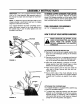
• To lower the hopper assembly to the ground, use one hand to grasp the top of the hopper assembly. Push down on the release handle, and pivot the hopper assembly to the right. See figure 8. Hopper Release Handle FIGURE 8. • Bulky materiar, such as stalks or heavy branches, up to 3" in diameter, should be fed into the chipper chute. See figure 9. WARNING: MAKE CERTAIN THE CHIPPER IN NOT CHUTE USE.
Check the fuel level periodically to avoid running out of gasoline while operating the chipper-shredder. If the unit runs out of gas as it is shredding or chipping, it may be necessary to unclog the unit before it can be restarted. Refer to "Removing the Flail Screen" in SERVICE AND ADJUSTMENT section. WARNING: EXPERIENCE INDICATES THAT ALCOHOL BLENDED FUELS (CALLED GASOHOL OR USING ETHANOL OR METHANOL) CAN ATTRACT MOISTURE WHICH LEADS TO SEPARATION AND FORMATION OF ACIDS DURING STORAGE.
• TO STOPENGINE • Move throttle control lever to OFF position. See figure 13. Disconnect spark plug wire and move away from spark plug to prevent accidental starting while equipment is unattended. ilUll =1 CUSTOMER iii iiii MAINTENANCE i i i RESPONSIBILITIES iiiiiiiiii SCHEDULE f_o_//_.3 AS YOU COMPLETE /oe'_'-/_'//- REGULAR SERVICE /@_//"_"+'_'/'_/ _ "/^_/-°'_-/-_'_/ "_/ "-/_<_'/ .... SERVICE DATES I-- o 0 Oil Pivot Points t' Clean Shredder "J -_ i.
To DrainOil: CLEAN ENGINE • Drain oil while engine is warm. a. Remove oil drain cap. Refer to figure 10. Catch oil in a suitable container. b. When engine is drained of all oil, replace drain cap securely. • Refill with fresh oil. Refer to GAS AND OIL FILLUP section. Clean engine periodically. Remove dirt and debris with a cloth or brush. Cleaning with a forceful spray of water is not recommended as water could contaminate the fuel system.
i ii i i i iii ill i ii i STORAGE Prepare your chipper-shredder for storage at the end of the season or if the unit wilt not be used for 30 days or more. • Drain the fuel tank. • Start the engine and let it run until the fuel lines and carburetor are empty. • Never use engine or carburetor c}eaner products in the fuel tank or permanent damage may occur. • Use fresh fuel next season.
Chute Replace or sharpen blades, Ff sharpening, make certain to remove an equal amount from each blade. Reassemble in reverse order. Hairpin Clips, Clevis Pins Make certain blades are reassembled with the sharp edge facing the direction shown in figure 18 (sharp edge is assembled toward the slotted opening in the impeller assembly). SHREDDING _- Hex Nuts Washers BLADE The shredding blade may be removed for sharpening or replacement as follows.
CARBURETORADJUSTMENT NOTE: Use caution when removing the blade to avoid contacting the weld bolts on the housing. WARNING: • When sharpening the blade, follow the original angle of gdnd as a guide. It is extremely important that each cutting edge receives an equal amount of grinding to prevent an unbalanced blade. An unbalanced blade will cause excessive vibration when ,_ rotating at high speeds and may cause damage to the unit. IF ANY ADJUSTMENTS ARE MADE TO ENGINE THE ENGINE IS THE RUNNING (E.G.
i TROUBLE SHOOTING PROBLEM POSSIBLE CAUSE(S) CORRECTIVE Engine • Fuel tank empty, or stale fuel. • Spark plug wire disconnected. • Faulty spark plug. • Fill tank with clean, fresh fuel. • Connect wire to spark plug. • Clean, adjust gap or replace. • • • Spar_
SEARS CRAFTSMAN Repair 5 H.P. CHIPPER-SHREDDER MODEL Parts 67 57 \ 19 5O 69 _ 6 !I 42 59 \ 16 NO. 247.
SEARS CRAFTSMAN 5 H.P. CHIPPER-SHREDDER MODEL NO. 247.795940 Repair Parts KEY NO. PART NO. 1 2 742-0571 710-1254 736-0217 736-0247 6 7 8 9 10 11 12 13 14 15 16 17 18 19 20 21 22 23 24 25 26 27 28 29 30 31 32 33 34 35 11459B 711-0564 711-0833A 711-0834 715-0249 736-0192 681-0030 781-0490 710-1054 712-0411 736-0119 710-0825 736-0142 750-0793 711-0835 731-1427 712-0291 714-3010 781-0457 714-0149B 781-0480 712-3010 736-0242 720-0170 747-0744A 732-0542 781-0489 781-0475 736-0170 712-3010 KEY NO.
TECUMSEH 5 H.P. ENGINE MODEL NO.
TECUMSEH 5 H.R ENGINE MODEL NO. HS50-67344G Repair Parts KEY NO. PART NO. 33674B 26727 34171 30969 28277 31334 31510 31335 650548 31426 32600 t33342 650561 75 8O 81 82 83 86 89 9O 92 93 100 101 DESCRIPTION Cylinder Ass'y. (Incl. Nos, 2 & 20) Pin, Dowel Oil Drain Extension OiPDrain Cap Washer, Flat Rod, Governor Lever, Governor Clamp, Governor Lever Screw, Hex Washer Hd. 8-32 x 5/16 Spring, Extension Seal, Oil Baffle, Blower Housing Screw, Hex Washer Hd. Durlok, 1/4-20 x 5/8 36421 Crankshaft Ass'y.
TECUMSEH 5 H.P, ENGINE MODEL NO. HS50-67344G Repair Parts KEY NO. PART NO. 277 285 287 650327 34694 650926 290 292 298 30962 26460 650665 3OO 35591 301 305 307 308 35355 35554 35499 35539 DESCRIPTION KEY NO, Screw, Hex Hd., 1/4-20 x 2-3/8 Cup, Starter Screw, Hex Washer Hd., 8-32 x 21/64" Line, Fuel Clamp, Fuel Line Screw, Hex Washer Hd. Thread Cutting, 1/4-15 x 7/8 Tank Ass'y., Fuel (Incl. Nos. 292 & 301) Cap Ass'y.
flANUALDEL 'ROPIETARIO NUMERO DE MODELO 247,795940 CRRFTSMRN 5 CABALLOS DE FUERZA 3 ETAPAS DE CORTE CUBRIDOR DE PAJA Y EMBOLSADOR PICADORA-DESMENUZADORA Precaucibn: Lea y observe todas las reglas e instrucciones de seguridadantes Armado de operar este Operacibn equipo Responsabilidades del Cliente Servicio y Ajuste Piezas de Reparacibn SEARS,ROEBUCK ANDCO.,HoffmanEstates,IL 60195U.S.A. preso en U.S,A.
REGLAS DE SEGURIDAD IA ADVERTENClA: PARA REDUClR EL POTENClAL DE CUALQUIER LESION CUMPLA CON LAS INSTRUCClONES DE SEGURIDAD SIGUIENTES. LA FALLA EN CUMPLIR CON LAS INSTRUCCLONES PUEDE RESULTAR EN LESlONES PERSONALES. ENTRENAMIENTO • Lea este manual del propietario cuidadosamente por completo antes de tratar de armar u operar esta mdquina. Est_ completamente familiarizado con los controles y el uso adecuado de esta m_.quina antes de operarla.
FELICITACIONES per su compra de una PicadoraDesmenuzadora Craftsman de Sears. Ha side dise_ada, planeada y fabricada par proporcionarle la confiabilidad y rendimiento mejor posible, Si tuviera alg0n problema que no se pudiera remediar fdcilmente, Ilame a su Centre/ Departamento de Servicio Sears mds cercano en los Estados Unidos. Tenemos tecnicos competentes, bien entrenados y las herramientas adecuadas para servir e reparar esta unidad. Per favor lea y guarde este manual.
TABLA DE MATERIAS REGLAS DE SEGURIDAD ......................................... ESPEClFICAClONES DEL PRODUCTO ................... ACUERDO DE MANTENIMIENTO ............................. RESPONABILIDADES DEL CLIENTE ....................... GARANTIA ................................................................. ACCESORIOS ............................................................ INSTRUCCIONES DE ARMADO ............................... ACCESORIOS 2 3 3 3 3 4 5 OPERACION .................................
INSTRUCCIONES IMPORTANTE: Esta unidad se envia SIN GASOLINA O ACEITE. Despu_s del armado, vea la seccibn de operaci6n de este manual para las recomendaciones del combustible y aceite del motor adecuados. NOTA: Para determinar los lados de mano derecha e izquierda de su picadora-desmenuzadora, parese detr_.s y enfrente la tolva (et motor esta al frente de la unidad), Su picadora-desmenuzadora ha sido completamente armada en la fabrica, excepto por deflector de la canaleta y la bolsa colectora.
ii ii i im H i OPERAClON i j CONOZCASU PICADORA-DESMENUZADORA LEA ESTE MANUAL DEL PROPIETARIO Y I_AS REGLAS DE SEGURIDAD ANTES DE OPERAR SU PICADO- RA-DESMENUZADORA Compare las ilustraciones con su picadora-desmenuzadora ubicaci6n de varies controles y ajustes. Guarde este manual para referencia futura. Conjunto de ta tolva para famifiarizarse con la Varilla para medir la profundidad de Ilenado de aceite Palanca del Palanca de Canaleta de la acelerador FIGURA 4. Bolsa FIGURA 3.
PARAAPAGAREL MOTOR Mds pequefio que 1/2" de didmetro (Recomendado) o 1" de di_imetro (M=iximo) • Mueva la palanca de control del acelerador a la posici6n OFF (APAGADO). Vea la figura 4. • Desconecte el cable de la bujfa y alejelo de la misma para evitar un arranque accidental mientras el equipo no est_ atendido. Conjunto de la tolva COMO USAR SU PICADORADESMENUZADORA No trate de picar o desmenuzar cualquier material diferente de vegetaci6n que se encuentra en cualquier patio normal (por ej.
picar. Si cambia la composicibn del material que est,_ siendo descargado (se convierte en tipo encordado, etc.) o disminuye considerablemente la velocidad a la cua! se descarga e! material, es posible que la cuchilta de desmenuzar y/o las cuchillas de picar est_n desafiladas y tengan que ser afiladas o reemplazadas. Refi_rase a [a seccidn de Servicio y Ajuste. • Para bajar la tolva alsuelo, agarre con una mano la parte superior del conjunto de la tolva.
GAS Varilla para medir la profundidad de Ilenado de aceite • Quite la tapa de combustible y Ilene el tanque con aproximadamente 1-7/8 cuartos de gasolina de autom6vil, limpia, fresca, sin plomo, de alto grado. NO USE Etilo o gasolina de alto octano. Asegt_rese de que el contenedor este limpid y libre de 6xido o particulas extra,as. Nunca use gasolina que est_ rancia por haberse almacenado pot un periodo largo en el contenedor. Vuelva a colocar la tapa de combustible.
• Mueva la palanca del regulador de aire a /a posiciSn CHOKE (REGULADOR). • Mueva el control del acelerador a la posicion IDLE (VACIO) para calentar por unos pocos minutos. Mueva la palanca del regulador a la posici6n RUN (FUNClONAR) a medida que el motor se calienta. • Tome la manija del encendido (yea la figura 14) y tire de fa cuerda lentamente hasta que el motor llegue al comienzo del ciclo de compresi6n (en este punto debera tirarse de la cuerda un poco m_.s fuerte).
Para drenar el aceite: •Drene mientras el motor esta caliente. a. Quite el tap6n de drenaje de aceite. Refi_rase a la figura 10. Recoja el aceite en un contenedor apropiado. b. Cuando se haya drenado et aceite del motor, reemplace seguramente et tap6n de drenaje. • Vuelva a Ilenar con aceite fresco. Refierase a la seccion de LLENADO DE GAS Y ACEITE. • Vuelva a colocar la varilla.
LIMPIEZA DEL MOTOR BUJIA La bujfa deberfa limpiarse y la distancia fijada nuevamente a .030" per Io menos una vez en la temporada o cada 50 horas de operacion. Vea ta figura 16. Se recomienda el reemplazo de la bujia al comienzo de cada temporada. Refierase a la lista de piezas del motor para el tipo correcto de bujia. Limpie peri6dicamente el motor. Quite la suciedad y testes con un trapo o cepillo.
NOTA:Un estabilizador de combustible es una alternativa aceptable para minimizar la formaci6n de dep6sitos de goma durante el almacenamiento. Agregue estabilizador a la gasolina en el tanque de combustible o en el contenedor de almacenamiento. Siga siempre la proporci6n de mezcla indicada en el contenedor del estabilizador. Haga funcionar el motor por 10 minutos por Io menos despues de agregar el estabilizador para permitir que el estabilizador Ilegu al carburador.
NOTA:La arandelaacopadaest& en el fondo de la canaleta de la picadora con la parte acopada contra la canaleta. NOTA: Aseg_rese, cuando est_ rearmando, de que la abertura en la plancha de respaldo enfrente el fondo de la unidad. Puede invertirse la plancha de respaldo para proveer un nuevo borde de core. • Rote a mane el conjunto del impulsor hasta que ubique una de las cuchillas de la picadora en la abertura de la canaleta de la picadora.
VELOCIDADDEL MOTOR la velocidad de su motor ha sido fijada en f_brica. No trate de aumentar la velocidad del motor ya puede resultar en lesiones personales. Si usted cree que el motor est& funcionando demasiado rapido o demasiado lento, Ileve su picadora-desmenuzadora al Centro de Servicio Sears ma.s cercano para reparar y ajustar. FIGURA 20. • Ajuste entre 550 y 650 pulgadas libras, cuando rearme la cuchilla, o ajuste segurarnente si no tuviera una Ilave indicadora de torsion.
LOCALIZACION i II PROBLEMA DE FALLAS I I ACCION CORRECTIVA CAUSA(S) POSIBLE El meier no se enciendet Perdida de potencia: operaci6n irregular • • El tanque de combustible est_ vacfo, o combustible rancio. • El cable de la bujfa est', desconectado. • • • Buj/a defectuosa. • El collie de la bujla est& flojo. • • La unidad est& funcionando en CHOKE. • • La Ilnea de combustible est,, btoqueada • o combustible rancio. F• • Agua o suciedad en el sistema de combustible. • Filtro de aire sucio.