OWNER'S MANUAL MODELNOS. 247.799891 247.799892 CRRFTSMRN Caution: ReadandFollow AllSafetyRules andInstructions BeforeOperating ThisEquipment 5 HORSEPOWER 3 CUTTING STAGE MULCHING AND BAGGING CHIPPER-SHREDDER Assembly Operation Customer Responsibilities Service and Adjustment Repair Parts SEARS,ROEBUCKAND CO., HoffmanEstates, IL 60195 U.S.A. )rinted in U.S.A.
SAFETY RULES _ SAFETY INSTRUCTIONS. WARNING: TO REDUCE PERSONAL INJURY. FAILURE TO COMPLY WITH THE THE POTENTIAL FOR ANY INJURY, TRAINING • Read this owner's manual carefully in its entirety before attempting to assemble or operate this machine. Be completely familiar with the controls and the proper use of this machine before operating it. Keep this manual in a safe place for future and regular reference and for ordering replacement parts. • Children must never be allowed to operate this equipment.
CONGRATULATIONS on your purchase of a Sears Craftsman Chipper-Shredder. It has been designed, engineered and manufactured to give you the best possible dependability and performance. Should you experience any problem you cannot easily remedy, please contact your nearest Sears Service Center/ Department in the United States. We have competent, welltrained technicians and the proper tools to service or repair this unit. Please read and retain this manual.
TABLE OF CONTENTS SAFETY RULES ......................................................... 2 PRODUCT SPECIFICATIONS ................................... 3 MAINTENANCE AGREEMENT .................................. 3 CUSTOMER RESPONSIBILITIES ............................. 3 WARRANTY ............................................................... 3 INDEX ......................................................................... 4 ASSEMBLY ................................................................
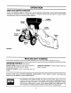
ASSEMBLY INSTRUCTIONS TOREMOVE CHIPPER-SHREDDER FROMCARTON IMPORTANT: This unit is shipped WITHOUT GASOLINE or OIL. After assembly, see operation section of this manual for proper fuel and engine oil recommendations. Cut the corners of the carton. Remove all packing inserts. Roll chipper-shredder out of the carton. Make certain all parts, literature and the safety glasses have been removed before the carton is discarded.
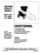
OPERATION KNOW YOUR CHIPPER-SHREDDER READ THIS OWNER'S MANUAL AND SAFETY RULES BEFORE OPERATING YOUR CHIPPER-SHREDDER. Compare the illustrations with your chipper-shredder to familiarize yourself with the location of various controls and adjustments. Save this manual for future reference. Hopper 31y Chipper Chute Chute Deflector Lever Control Catcher Bag Starter Handle FIGURE 3.
TO STOP ENGINE No Larger 1/2" Diameter (Recommended) Or 1" Diameter (Maximum) • Move throttle control lever to OFF position. See figure 4. • Disconnect spark plug wire and move away from spark plug to prevent accidental starting while equipment is unattended. Hopper Assembly Tt Control FIGURE 5. FIGURE 4. • Bulky material, such as stalks or heavy branches, up to 3" in diameter, should be fed into the chipper chute. See figure 6.
GASAND OIL FILL-UP OIL Only use high quality detergent oil rated with API service classification SG. Select the oil's viscosity grade according to your expected operating temperature. Colder _ 32°F m Warmer NOTE: Although multi-viscosity oils (5W30, 10W30, etc.) improve starting in cold weather, these multiviscosity oils will result in increased oil consumption when used above 32°F. Check your oil level more frequently to avoid possible engine damage from running low on oil.
• Attach spark plug wire and rubber boot to spark plug if necessary. See figure 8. Choke • Place the throttle control lever in FAST position. See figure 9. • Move choke lever to CHOKE position. ) • Grasp starter handle (see figure 9) and pull rope out slowly until engine reaches start of compression cycle (rope will pull slightly harder at this point). Let the rope rewind slowly. OFF RThroffie NOTE: A noise will be heard when finding the start of the compression cycle.
GENERALRECOMMENDATIONS AIR CLEANER The air cleaner prevents damaging dirt, dust, etc., from entering the carburetor and being forced into the engine and is important to engine life and performance. WARNING: ALWAYS STOP THE ENGINE AND DISCONNECT THE SPARK PLUG WIRE BEFORE PERFORMING ANY MAINTENANCE OR ADJUSTMENTS. • Periodically are tight. • Never run your engine without pletely assembled. check all fasteners and be sure they To Service Air Cleaner: Follow the Maintenance page.
NOTE: Do not sandblast spark plug. Spark plug should be cleaned by scraping or wire brushing and washing with a commercial solvent. WARNING: PERIODICALLY CLEAN MUFFLER AREA TO REMOVE ALL GRASS, DIRT AND COMBUSTIBLE DEBRIS. CLEANING • The chipper-shredder may be cleaned by running water from a hose through the hopper assembly and chipper chute with the engine running. Allow the chipper-shredder to dry thoroughly. .030" Feeler Gauge \ • Wash the bag periodically with water.
NOTE:Fuelstabilizeris an acceptablealternativein minimizingthe formationof fuelgumdepositsduring storage.Addstabilizerto gasolinein fueltankor storagecontainer.Alwaysfollowthe mix ratiofoundon stabilizercontainer.Runengineat least10 minutes afteraddingstabilizerto allowthe stabilizerto reach thecarburetor. Donotdrainthegastankandcarburetorif usingfuelstabilizer. • Drainall the oilfromthecrankcase(thisshouldbe doneaftertheenginehasbeenoperatedandis still warm)andrefillthecrankcase withfreshoil.
NOTE: Use caution when removing the blade to avoid contacting the weld bolts on the housing. Replace or sharpen blades. If sharpening, make certain to remove an equal amount from each blade. Reassemble in reverse order. • When sharpening the blade, follow the original angle of grind as a guide. It is extremely important that each cutting edge receives an equal amount of grinding to prevent an unbalanced blade.
The carburetor may need re-adjusting if engine lacks power or does not idle properly. If adjustments are needed, proceed as follows. Throttle Idle Speed ustin_ • Close needle valve (see figure 17) clockwise (F_) finger tight only. Forcing may cause damage. Then open 1-1/2 turns counterclockwise (f"). • Start engine and allow to warm for five minutes. • With throttle in FAST position, close needle valve clockwise (_) until engine starts to lose speed (lean mixture).
TROUBLE SHOOTING PROBLEM POSSIBLE CAUSE(S) CORRECTIVE Engine fails to start • • • Fuel tank empty, or stale fuel. Spark plug wire disconnected. Faulty spark plug. • • • Loss of power; operation erratic • • • Spark plug wire loose. Unit running on CHOKE. Blocked fuel line or stale fuel. • • • • Water or dirt in fuel system. • Carburetor out of adjustment. • Dirty air cleaner. • Carburetor not adjusted properly. Engine oil level low. • Contact your SEARS Service Center.
SEARS CRAFTSMAN 5 H.P. CHIPPER-SHREDDER MODEL NOS. 247.799891 Repair Parts 247.
SEARS CRAFTSMAN 5 H.P. CHIPPER-SHREDDER MODEL NOS. 247.799891 Repair Parts KEY NO. 1 2 PART NO. 742-0571 710-0818 710-1254 714-0114 4 5 6 7 8 9 10 11 12 13 14 15 16 17 18 19 20 22 23 24 25 26 27 28 29 30 247.799892 736-0217 736-0247 11459B 711-0564 711-0833A 711-0834 715-0249 736-0192 681-0002 681-0030 781-0490 710-1054 712-0411 736-0119 710-0825 736-0142 750-0793 711-0835 712-0291 714-3010 781-0457 714-0149B 781-0480 712-3010 736-0242 720-0170 747-0744A KEY NO.
BRIGGS AND STRATTON 5 H.P. ENGINE MODEL NOS. 135212-0272-01 Repair Parts REF. NO. PART NO. 135212-0140-01 DESCRIPTION 373 55 56 57 58 494846 493824 262594 280406 59 60 65 69 69A 373 456 459 461 515 608 1016 396892 393152 94686 280973 224322 92987 224321 492833 262626 262625 495766 224278 REF. NO. PART NO.
BRIGGS AND STRATTON 5 H.P. ENGINE MODEL NOS. 135212-0272-01 Repair Parts REF. NO, 52 9O 95 96 97 108 118 124 127 127A 149 152 154 202 2O3 205 392 394 432 433 434 435 611 634 679 680 987 135212-0140-01 PART NO. DESCRIPTION *-271936 495426 93499 223793 490048 491177 231533 94616 220352 223789 26336 260575 93527 262270 280720 231520 262328 .
BRIGGS AND STRATTON 5 H.P. ENGINE MODEL NOS. 135212-0272-01 Repair Pa rts REF. NO. 12 18 19 20 21 22 25 26 27 28 29 30 32 45 46 219 220 227 23O 562 592 614 615 616 _45 PART NO. *270080 *270125 *270126 493916 495660 *298504 66768 94682 298904 298905 298906 298907 298982 298983 298984 298985 26026 298909 298908 299430 221890 94745 260642 212733 494845 221551 490374 222450 92613 231082 93306 93307 231077 REF. NO. PART NO.
BRIGGS AND STRATTON 5 H.P. ENGINE MODEL Repair Parts REF. NO. PART NO. 1 5 7 8 9 10 11 13 14 395990 214040 *272157 495774 *27549 94621 66578 94221 94679 15 16 94387 495649 495845 33 34 35 36 4O 306 307 308 337 383 527 528 529 552 635 741 869 870 871 REF. NO.