owners manual MODEL NO. 247.88110 CAUTION: Read SAFETY RULES and INSTRUCTIONS carefully CRAFTSMAN HI WHEEL SELF PROPELLED ROTARY MOWER • Assembly • Operating • Maintenance • Repair Parts Sold by SEJARS, ROEBUCK AND CO« dilcagojll. 60607 USA. Etnd SIMPSONS-SBARS LIMITBD. Toronto PART NO. 770-4447 PRINTED IN U. S.A.
IMPORTANT SAFE OPERATION PRACTICES FOR WALK-BEHIND MOWERS TRAINING 1. Read the Operating and Service Instruction Manual 5. If the equipment should start to vibrate abnormally, stop the engine (motor) and check immediately for 6. Stop the engine (motor) whenever you leave the equipment, before cleaning the mower housing, and carefully. Be thoroughly familiar with the controls 2. 3. and the proper use of the equipment. Never allow children to operate a power mower. the cause.
iMHWMMWiiwwmwmt CRAFTSMAN 1-YEAR GUARANTEE If during the first year this Craftsman product fails to give proper performance due to defects in material or workmanship, we will make all necessary repairs, free of charge. This guarantee service is available through any of our stores or service centers through out the United States or Canada. MMöMMMMiMMMMMM MAINTENANCE AGREEMENT A MODERN, LOW-COST MAINTENANCE AGREEMENT IS AVAILABLE ON THIS PRODUCT TO EXTEND THE GUARANTEE. CONTACT YOUR NEAREST SEARS STORE.
REFERENCE PHOTO FOR ASSEMBLY AND INSTRUCTIONS Upper Handle (2) L Throttle Control Grips (2) K;Handle Panel / Blade Engaging Lever (Under Handle ', Panel) Lower Handle (One Piece) L. H Brace Starter Handle Throttle Control Cable. / XOil Fill and Drain Left Side of Engine R.H.
INDEX Safe Operation Practices___________________________ 2 Guarantee Maintenance Agreement Customer's Responsibilities Set-Up Instructions------------------------------------------------------ 3 Reference Photo Bolt Measurement Chart List of Contents in Hardware Pack--------------------------------- 4 Index Assembly Instructions______________________________5 Controls ________________________________________ 10 Operation ______________________________________ 11 To Start the Engine Efficient Operation ----
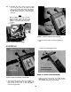
Step 2. a. Lower Handle Place the right hand brace in position on frame and secure with one (1) Hex Hd. Bolt 14-20 x 2Vi". Refer to figures 6 and 7. NOTE: Do not tighten. (2) Flatwashers %" I.D. X 1 'A" O.D. Hex Hd. Bolt— --16x 1' Adjustable Wrench FIGURE 5 LOWER HANDLE ASSEMBLY Fram Step 1. a. Place the lower handle in position on the frame. b. Place two (2) flat washers %" I.D. x 114" O.D. between the handle and frame only on the right hand side. See figure 5. c.
d. Secure the two (2) upper handles together with one (1) Hex Hd. Bolt % - 2 0 x l % " and one (1) Hex Center Lock Nut '/4-20 Thd. NOTE: Do not tighten. See figure 8. e. Place the two (2) upper handles assembled in position with the lower handle. See figure 9. FIGURE 10. THROTTLE CLAMP ASSEMBLY Step 3. a. FIGURE 9. HANDLE AND BRACE ASSEMBLY f. Place a bolt, regardless of length, in the top hole of the lower handle to help hold handle in po sition when working. g.
b. Secure two (2) Self Tapping Screws 8-32 x ’/2" holding throttle control to handle with a screw driver tightly. See figure 13. Step 5. a. Place the handle panel with throttle control at tached in position on handle assembly. See fig ure 14. Handle Panel Si Hex Center Lock Nut '4-20 Thd. FIGURE 12. LOCKOUT BRACKET ASSEMBLY d. Place the lockout bracket assembly under the "T" portion of the upper handle with the bolt ends facing up. See figure 12. e.
b. Secure bottom of handle panel to handle as sembly with two (2) Hex Hd. Bolts Va-2Q x 1 '/2" and two (2) Hex Center Lock Nuts '/4-20 Thd. See figure 14. c. Secure top of handle panel to speed nut with one (1) Truss Hd Machine Screw 10-24 x %" Long. See figure 15. 'russ Hd. Mach. Screw 10-24 X 3s" Lg. ■^7*----- Handle FIGURE 16 DRIVE PINION CLEARANCE |W/S$HtR BOLTS i. li LOCKOUT lever FIGURE 15. HANDLE PANEL ASSEMBLY TO HANDLE Step 6. a.
Step 7. Assemble the other control rod and lockout lever to the pivot lever on the lower Left Hand side of the mower with ferrule and washer. Assemble the lockout lever to the upper han dle with washer and nut as shown in figures 18 and 19. art Position Away from Operator^ NOTE With the blade lockout lever in the dis engaged position, adjust the rod in the ferrule so that there is just enough resistance to hold the blade lockout lev er in place. BLADE rCNTKI 1 LOCKOUT I EVER FIGURE 21.
OPERATION CAUTION Stop the engine and disconnect the spark plug wire from the spark plug before making any adjustments. See figure 25. Lockout Lever Engaged Position FIGURE 23. DRIVE MECHANISM ENGAGED FIGURE 25. SPARK PLUG WIRE BEING REMOVED 1. Blade Spindle Assembly—The blade spindle as sembly is equipped with a grease fitting. Use grass discharge chute for access to the fitting located un der the deck. Use multi-purpose grease. Lubricate PRIOR to initial use and every 25 hours thereafter.
2. Service engine with clean fresh regular gasoline. TO START THE ENGINE 3. 1. Be sore the engine has been serviced with the pro per oil and fuel. Service engine with SAE 30 weight motor oil. Fill oil fill opening to overflow. See figure 27. 2. Move the lockout lever to the DISENGAGED posi tion. 3. Move the throttle control lever to the START posi tion. 4. Place one foot on the left side of the deck. See fig ure 28. 5.
2. The deck may be cleaned by tilting the mower backward or on its side and scraping clean with a suitable tool or by washing with a stream of wa ter from a garden hose. Lower Support CAUTION Do not direct the stream of water at a hot engine as damage to the engine may result. 3. For best results do not cut wet grass because it tends to stick to the underside of the mower, thus pre venting proper discharge of grass clippings.
2. Remove the hex lock nut holding the lockout lever in position. 3. Turn the lockout rod and lever in or out of the fer rule until the lockout lever lines up with the lock out bracket. 4. Secure lockout lever in position with hex lock nut. CAUTION Stop the engine and disconnect the spark plug wire from the spark plug before making any adjustments. 1. Cutting height adjustment is made by removing and moving axle bolts to the desired positions.
1. Throttle Control—If throttle adjustment becomes necessary, the throttle control wire may be reset as follows: a. Loosen, but do not remove, screw securing throt tle control wire assembly at engine. b. Move throttle control lever on handle to START position. c. Move lever to which control wire is fastened to engine to full START position. Retighten screw to secure throttle control wire assembly. See fig ure 34. FIGURE 35.
5. Blade Spindle Assembly ENGINE LUBRICATION The blade spindle assembly, located on the underside of the mowing deck, is equipped with a grease fitting Use grass discharge chute for access to the fitting lo cated under the deck. Use multi-purpose grease. Lubri cate prior to initial use and every 25 hours thereafter. See figure 36. CAUTION Stop the engine and disconnect the spark plug wire from the spark plug before making any adjustments. CAUTION Be sure spark plug wire is disconnected and grounded.
7. NOTE Tip mower on its right hand side and remove the oil drain plug. Always tip engine toward oil drain hole. Be sure oil drains completely. Replace oil drain plug and refill rected on page 1, or engine nameplate. 3. oil as di CHECK OIL every nve (5) operating hours or each time equipment is used. a. 4. with If engine has dip stick, keep indicated by adding if necessary.
CARBURETOR ADJUSTMENTS STORAGE INSTRUaiONS Do not make unnecessary tings are correct for most are needed, proceed as follows: 1. adjustments. Factory set applications. If adjustments Close power adjusting needle (figure 42) by turning to right (clockwise). tight only. Forcing will cause damage. 41 or Close In event engine is to be stored for any length of time (30 days or more) or at the end of mowing season, pre pare as follows: figure finger 1.
TROUBLE SHOOTING CHART CAUTION: ALWAYS DISCONNECT SPARK PLUG BEFORE ATTEMPTING ANY REMEDY. TROUBLE REMEDY LOOK FOR Blocked fuel line or empty gas tank. Clean fuel line; check fuel supply. Defective plug. Spark plug lead wire disconnected. spark Faulty spark plug—spark should electrode and side electrode. If place spark plug. Engine fails to start. jump spark gap between control does not jump, re NOTE: Use insulated pliers 1o hold the spark plug wire. Hard starting power.
CRAFTSMAN HI WHEEL SELF-PROPELLED ROTARY MOWER MODEL 247.
CRAFTSMAN HI WHEEL SELF-PROPELLED ROTARY MOWER MODEL 247.88110 M REF. NO. PART NO. 1 2 3 4 5 6 712-107 8378 9354 720-157 7889 8373 7 8 9 711-180 8376 736-108 10 11 12 13 14 15 16 17 18 19 712-107 712-107 710-106 710-606 712-107 9362 8327 712-130 738-234 9372 DESCRIPTION Hex Center Locknut 14-20 Thd. Clamp Bracket Upper Handle (2-Req'd.) Grip Plastic Ball Lockout Lever Ass'y- with Plastic Ball Control Rod Lockout Bracket Ass'yFlat Washer .510" I.D. x .75" O.D. X .033 Hex Center Locknut 14-20 Thd.
CRAFTSMAN HI WHEEL SELF-PROPELLED ROTARY MOWER MODEL 247.
CRAFTSMAN HI WHEEL SELF-PROPELLED ROTARY MOWER MODEL 247.88110 M u REF. NO. PART NO. 1 2 3 4 5 6 7 8 710-121 736-114 748-108 748-136 7146 748-110 8187-347 710-148 9 10 11 12 13 14 15 16 17 18 19 20 748-135 711-180 711-179 8331 8189 710-289 736-329 710-252 8348 748-110 710-421 715-247 21 22 23 7120 711-415 736-300 24 25 26 714-121 736-329 712-287 '¿/ 1100/-J4/ 28 29 711-169 736-108 30 31 32 33 34 35 36 8772-347 712-287 736-329 748-226 8774-347 9927 714-229 DESCRIPTION Hex Scr. ’/2-20 X .
'//■
CRAFTSMAN HI WHEEL SELF-PROPELLED ROTARY MOWER MODEL 247.88110 REF. NO. 1 M (II PART NO. 710-117 2 3 4 5 6 7 8 9 10 11 710-158 8279-347 710-209 710-567 736-329 11446-347 11197-347 713-132 741-113 738-114 12 13 14 15 16 17 18 19 11141-347 732-253 726-106 11130-347 711-555 10769 734-438 734-180 734-391 20 21 741-114 738-213 DESCRIPTION Hex Scr. 5/16-24 x 1.00" Lg. Heat Treated Hex Scr. 5/16-24 X 1.25" Lg.* Frame Ass'y-—Complete Hex Sems Scr. %-16 x .62" Lg.* Hex Sems Scr. 14-28 x %" Lg.
BLADE SPINDLE ASSEMBLY 901-7805 2. Zerk Fitting should face Discharge Chute of Deck. 3. Lubricate every 8 to 10 hours with Shell General Purpose Grease or Equivalent. BLADE IDLER BRACKET ASSEMBLY DETAIL Brake Shoe 754-647 Rivet 728-649 Bracket Assembly 8298 Idler Bearing 756-370 Hex Lock Nut >12-372 BELT WEAR Belt Clip 7353 Belt clips improperly positioned will cause premature belt wear. The belt clip must completely clear the belt when the belt is tightened.
p Must Not Toiiti]^ Where Blade Is 27
NOTES: 28
NOTES 29
TECUMSEH 4-aCLE ENGINE MODEL NUMBER: V60-70259H f------ 137 30
TECUMSEH 4-CYCLE ENGINE Ref. No. Part No. 1 33361 2 4 5 27652 27876B 27877A 5 27880A 6 27878A 6 27880A 7 8 9 11 27882 27881 32581 33799 12 13 14 29783 27884 33312 14 33313 14 33314 15 15 15 16 17 33315 33316 33317 27888 31380B 18 19 20 21 22 30682 26073 28264 27893 33157 23 24 *30684 31471B 25 27 31355 29117 28 29 34 35 31356 27642 27897 650548 36 39 31335 650488 43 44 47 48 49 27625 *29673 *28938B 30938A 30939A MODEL NUMBER: V60-70259H Part Name Cylinder Assy. (Incl. Nos.
TECUMSEH 4-CYCLE ENGINE Ref. No. Part No. 113 114 115 30588A 27793 28942 117 118 119 30622 31752 650128 121 30688 122 123 124 126 27275 650490 8116 32584 127 128 129 131 32387A 32125 590417 29747A MODEL NUMBER: V60-70259H Ref. No. Part Name Spool, Governor Clip, Conduit Screw & Lockwasher, Slotted hex.hd., 10-32 x 3/8 Extension, Blower housing Decal, Air cleaner Screw, Fil. slotted hd. Sems, 10-24x1/2 Screw, Hex hd.
MAGNETO NO. 610689A Ref. No. 1 2 3 4 5 6 7 8 9 Part No. 610689A 30555 30551 30550 33695 30992 30547A 610385 610408 29181 Part Name Magneto Flywheel Spring, Breaker box dust cover Cover, Breaker box dust Gasket, Dust cover Cam, Breaker Breaker Assembly Washer, Terminal Nut, Terminal Screw and Washer Assembly, Breaker 33 Ref. No. Part No.
Ref. No. Part No. 1 2 3 4 5 6 7 8 9 10 11 12 631444 31834 631279 631036 650506 630766 650417 630973 630739 631037 *630748 *631027 *631021 13 14 15 631022 631023 *631024 Part Name Carbxiretor Shaft & Lever Assy., Throttle Spring, Throttle return Shutter, Throttle Screw, 4-40 x 3/16 Spring, Idle regulating screw Screw, Idle regulating Shaft & Lever Assy., Choke Washer, Flat Shutter, Choke Plug, Welch Plug, Welch Inlet Needle, Seat & Clip Assy. (Inch No.
REWIND STARTER NO. 590420 Ref. No. 1 2 3 4 5 6 Part No. 590420 590409 590410 590411 590148 590412 590413A Part Name Starter, Rewind Screw, Retainer Retainer, R.H. Spring, Brake Dog, Starter Spring, R.H. dog Pulley Ref. No. 7 8 9 10 11 Part No. 590414 590415 590386 590387 590459 Part Name Spring & Keeper Assy. Housing Assy., Starter Rope, Starter Handle Assy.
How to ORDER Repair Parts owners manual The Model Number will be found on a plate attached to your mower at the right-hand side of the frame. Always mention the Model Number when requesting service or repair parts for your 22 INCH HI WHEEL SELF PROPELLED ROTARY MOWER. All parts listed herein may be ordered through SEARS, ROEBUCK AND CO. or SIMPSONS-SEARS LIMITED.