Operator's Manual CRRFr MRN 28" SNOW THROWER Model No. 247.883950 ,, SAFETY o ASSEMBLY OPERATION MAINTENANCE PARTS LIST o ESPANOL CAUTION" Before using this product, read this manual and follow all safety rules and operating instructions. Sears Brands Management Corporation, Visit our website: Hoffman www.craftsman.com Estates, IL 60179, U.S.A. FormNo.
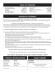
Warranty Statement .................... Safe Operation Practices .............. Assembly ......................... Operation ........................ Service &Maintenance .............. Off-Season Storage ................... Page 2 Pages 3-6 Pages 8-13 Pages 14-17 Pages 18-23 Page 24 CRAFTSMAN Troubleshooting ...................... Parts List ......................... Repair Protection Agreement ............ Espa_ol ............................. Service Numbers ...................
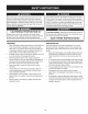
This machinewas builtto be operatedaccordingto the safeoperation practicesin this manual.As with anytype of powerequipment, carelessnessor error on the partof the operatorcan resultin serious injury.This machineis capableof amputatingfingers,hands,toes and feet and throwingdebris.Failureto observethe followingsafety instructionscouldresultin seriousinjuryor death. This symbolpointsout importantsafetyinstructionswhich,if not followed,couldendangerthepersonalsafetyand/orpropertyof yourselfand others.
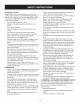
Safe Handling of Gasoline Toavoidpersonalinjuryor propertydamageuseextremecare in handlinggasoline.Gasolineis extremelyflammableand the vaporsare explosive.Seriouspersonalinjurycan occurwhengasolineis spilled on yourselfor yourclotheswhichcan ignite. Washyour skin and changeclothesimmediately. • • • Neverremovegas capor add fuel whilethe engineis hot or running. • • Allowengineto coolat leasttwo minutesbeforerefueling. Neveroverfill fueltank.
MAINTENANCE & STORAGE • Nevertamperwith safetydevices.Checktheirproperoperation regularly.Referto the maintenanceand adjustmentsectionsof this manual. • Beforecleaning,repairing,or inspectingmachinedisengageall controlleversand stop the engine.Wait untilthe auger/impeller cometo a completestop.Disconnectthe sparkplug wireand groundagainsttheengine to preventunintendedstarting. Checkboltsand screwsfor propertightnessat frequentintervals to keepthe machinein safe workingcondition.
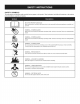
SAFETY SYMBOLS This pagedepictsand describessafetysymbolsthat mayappear on this product. Read,understand,and followall instructionson the machine beforeattemptingto assembleand operate. .i + i READ THE OPERATOR'S MANUAL(S) Read, understand, and follow all instructions in the manual(s) before attempting to assemble and operate WARNING-- ROTATING BLADES Keep hands out of inlet and discharge openings inside WARNING-- machine is running. There are rotating blades while machine is running.
Thispageleftintentionally blank.
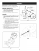
NOTE:Referencesto rightor left sideof the snowthrowerare determinedfrom behindthe unit in the operatingposition(standing directlybehindthe snow thrower,facingthe handlepanel). t Chute Control Head REMOVING 1. 2. 3. FROM CARTON Cut the cornersof thecarton and lay the sidesflat on the ground. Removeand discard all packinginserts. Movethe snowthrowerout of thecarton. Makecertainthe carton has beencompletelyemptiedbefore discardingit. ASSEMBLY 1.
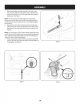
4. 5. Placechuteontochute baseand ensurechute control rodis positionedunderhandle panel.Installhex boltpreviouslyremoved but do not securewith wingnut at this time.See Figure4. Squeezethe triggeron thehandle paneljoystickand rotatethe chuteby hand to face forward.Theholes in the chutecontrol input will be facing up.See Figure5. f Chute Controlf NOTE:The chutewill not rotatewithoutsqueezingthe triggeron the joystick. 6.
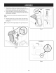
. Makesureall cables are routedto the left of the chutecontrol rod.Line up the hole in the rod with thearrowon the inputshaft and insertthe end of the rod into the inputshaftbelowjoystickon handlepanel.See Figure7. /i _ NOTE:Thechute controlrod will fit snugglyintothe inputshaft. Supportthe rear of thedash panelwith one handwhileinsertingthe rod with yourotherhandto ensurethe rod is insertedell the way into the input shaft. 8.
10. Checkthatall cablesare properlyroutedthroughthecable guide on the engine.See Figure10. "_ / NOTE:If the chute controlis not assembledcorrectlyit will not move freelynor will it movefully to the rightand left. 11. Theextensioncordfor the electricstarteris fastenedwith a cable tie to the rear of theauger housingfor shippingpurposes.Cut the cabletie and removecordbeforeoperatingthe unit. SET-UP Shear Pins Holesare locatedin the handlepanelfor convenientshearpin storage. See Figure11.
Chute Clean=Out Tool A chute clean-out tool is fastenedto the top of the augerhousing with a mountingclip. See Figure12.The tool is designedto cleara chuteassemblyof ice and snow.This item is fastenedwith a cabletie at the factory.Cut thecable tie beforeoperatingthe snowthrower. // Chute Clean-out loft _1 .allmoving_oarts have stoppedbeforeusingthe clean-outtool to clearthe chuteassembly. Tire Pressure Underanycircumstancedo notexceed manufacturer'srecommendedpsi.
Priorto operatingyoursnowthrower,carefullyread and followall instructionsbelow.Performall adjustmentsto verifyyoursnow throweris operatingsafelyand properly. I Checktheadjustmentof the augercontrolas follows: 1. 2. 3. 4. Theaugercontrol is locatedon the left handle.See Figure11 inset.Whentheauger controlis releasedand in the disengaged "up"position,the cableshouldhavevery little slack. It should NOT be tight. In a well-ventilatedarea,start the snowthrowerengine.
f Shift Lever Drive Control J / Four=WayChuteControP (Joystick) )...................AugerControl Headlight Gas C_ -Wheel \ Steering ControJ ChuteAssembly \\ Drift Cutter Muffler \ Primer CJeanOut Tool Recoil Starter Handle Oil Fill Auger HOUSe, Choke Control Throt Control Augers _ Skid Shoe Oil Drain ,_J Figure15 Nowthat youhaveset up yoursnowthrower,it's importantto become acquaintedwith its controlsand features.Referto Figure15.
THROTTLE CONTROL The augercontrol is locatedon the left handle.Squeezethe control grip againstthe handleto engagethe augerand startsnowthrowing action.Releaseto stop. DRIVE CONTROL/AUGER Thethrottlecontrolis locatedon the rearof the engine.It regulatesthe speedof theengine and will shutoff the enginewhenmovedintothe STOPposition. RECOIL STARTER CONTROL LOCK DRIVE CONTROL HANDLE This handleis usedto manuallystartthe engine.
CLEAN-OUT TOOL • • Neveruseyourhandsto cleara cloggedchuteassembly.Shut loft engineand remainbehindhandlesuntil all movingparts have lstopped beforeusingtheclean-outtool to clearthe chuteassembly. • Thechute clean-outtool is convenientlyfastenedto the rear of the augerhousingwith a mountingclip. Shouldsnowand ice become lodgedin thechute assemblyduringoperation,proceedas followsto safelycleanthechute assemblyand chute opening: 1. Releaseboththe AugerControland the DriveControl. 2. 3. 4. 5. 6. )or.
2. Movethrottlecontrolto FAST(rabbit)_J_" position. 3. Movechoketo the CHOKE I,'_1 position(coldenginestart). If engineis warm,placechokein RUNposition. 4. Pushprimerthree (3) times, makingsureto covervent hole in primerbulbwhen pushing.If engineis warm,pushprimeronly once.Alwayscover venthole whenpushing.Coolweathermay requireprimingto be repeated. Pushstarterbuttonto start engine.Oncethe enginestarts,immediatelyreleasestarterbutton.
MAINTENANCE Beforeperforminganytype ofmaintenance/service, disengageall controlsand stoptheengine.Waituntilall movingpartshavecometo a completestop.Disconnectsparkplugwireandgroundit againstthe enginetopreventunintendedstarting.Alwayswearsafetyglassesduring operationor whileperforminganyadjustmentsor repairs. EachUseand every 5 hours 1st5 hours SCHEDULE Followthe maintenanceschedulegiven below.This chart describes serviceguidelinesonly. Usethe ServiceLog columnto keeptrackof completedmaintenancetasks.
. 6. Reinstallthe drain plugand tightenit securely. Refillwith the recommendedoil and checkthe oil level.See RecommendedOil Usagechart.Theengine'soil capacityis 37 ounces. i u [ (%-40 °-20 o 0o 200 400 ("c) Oil Drain Plug -300 -200 -10° 0° DO NOTuse nondetergentoil or 2-strokeengineoil. It could shorten the engine'sservicelife. 7. Reinstallthe oil fillercap/dipsticksecurely. Figure18 Thoroughlywashyour handswith soap andwater as soonas possibleafter handling usedoil.
hotandcan ine. LUBRICATION O i Gear Shaft Thegear (hex)shaft shouldbe lubricatedat least oncea seasonor afterevery 25 hoursof operation. 1. Topreventspillage,removeall fuel fromtank by runningengine until it stops. 2. 3. 4. Carefullypivotthe snowthrowerup and forwardso that it restson theauger housing. Removethe lowerframecover fromthe undersideof the snow throwerby removingthe self-tappingscrewswhich secureit. Applya lightcoatingof engineoil (or 3-in-1oil) to the hexshaft. See Figure21.
ADJUSTMENTS Shift Cable If thefull rangeof speeds(forwardand reverse)cannotbe achieved, referto the figureto the rightand adjustthe shift cableas follows: 1. Placethe shiftleverin thefastest forward speedposition(F6). 2. Loosenthe hex nuton the shiftcable indexbracket.See Figure 24. 3. 4. Pivotthe bracketdownwardto take up slack in the cable. Retightenthehex nut. Drive Control Whenthedrivecontrol is releasedand in thedisengaged"up"position, the cableshouldhavevery little slack.It shouldNOTbe tight.
Auger Control Referto the Assemblysectionfor instructions on adjustingtheauger controlcable. Skid Shoes Referto the Assemblysectionfor instructions on adjustingthe skid shoes. BELT REPLACEMENT Auger Belt To removeand replaceyoursnow thrower'sauger belt, proceedas follows: 1. Topreventspillage,removeall fuel fromtank by runningengine until itstops. 2. Removethe plasticbelt coveron the front of the engineby removing the two self-tappingscrews.See Figure27. Rollthe auger beltoff theengine pulley.
7. Remove thebeltfromaround theauger pulley, andslipthebelt between thesupport bracket andtheauger pulley. SeeFigure 31. 8. Reassemble auger beltbyfollowing these instructions inopposite order andmanner ofremoval. 9. Perform theAuger Control testoutlined intheAssembly section ofthismanual. iO i NOTE: DoNOT forget toreinstall theshoulder screw andreconnect thespring totheframe afterinstalling areplacement auger belt. Drive Belt Toremoveand replaceyoursnow thrower'sdrivebelt, proceedas follows: 1.
If the snowthrowerwillnot be usedfor30 daysor longer,or if it is the end of the snowseasonwhenthe last possibilityof snowis gone,the equipmentneedsto be storedproperly.Followstorageinstructionsbelowto ensuretop performancefrom the snowthrowerfor manymoreyears. PREPARING PREPARING ENGINE Whenstoringthe snowthrowerin an unventilatedor metal storage shed,careshouldbe taken to rustprooftheequipment.Using a light oil or silicone,coat theequipment,especiallyanychains, springs,bearingsand cables.
Enginefails to start 1. 2. Chokecontrolnot in CHOKEposition. Sparkplugwire disconnected. 1. 2. Movechokecontrolto CHOKEposition. Connectwireto sparkplug. 3. 4. 5. Faultysparkplug. Fueltank emptyor stalefuel. Enginenot primed. 3. 4. 5. Clean,adjustgap,or replace. Filltank with clean,freshgasoline. Primeengineas instructedin the OperationSection. 6. 7. Keynot inserted. Extensioncordnot connected(when usingelectricstartbutton,on modelsso equipped). 6. 7. Insertkeyfully intothe switch.
Craftsman Snow Thrower Model 247.
Craftsman Snow Thrower IViodel 247.883950 D = 731-2635 2. 0 0 I SnowRemovalToolMount 684-04057A-0637 ImpellerAssembly,12"Dia. L Hex Screw,3/8-16, 1.75,Gr5 = O O 684-04108-4044 Spiral Assembly,RH 31. 731-04870 Spacer,1.25OD x .75ID x 1.00 32. 736-0188 Washer,Flat,.76x 1.49x .06 Bushing,Flange,.80ID x .91OD 3. L710-0347 4. 710-0451 Bolt, Carriage,5/16-18,.750Grl 33. 741-0493A 5. 710-04484 Screw, 5/16-18,0.750 34. 790-00087A-0637 Housing,1"Hex Bearing 6.
Craftsman Snow Thrower IViodel 247.
D _ W 684-04112C HandleEngagementAssemblyRH 2. 738-04367 FlangeShoulderScrew 3. 731-04894D LockPlate 4. 684-04250 PivotRod 5. 935-0199A RubberBumper 6. 710-3069 Screw,1/4-20x .500 7. 731-04896B ClutchLock Cam 8. 712-04081A ShoulderNut, 1/4-20 9. 710-0627 10. 731-06440A D _ O O 710-0262 CarriageBolt,5/16-18x 1.50 43. 631-04133A HandleClutchLock LHAssembly 44. 684-04111B HandleEngagementAssemblyLH 45. 784-5594-0637 Cable Bracket 46. 920-0284 Wing Knob 47.
// I i iL51 ) 128; _:7¢ 3O
D_ i B O ¸ 710-1652 AB Screw,1/4-20x 0.625 2. 731-06401 BeltCover 3. 735-04099 4. m _ O 684-04159 FrictionWheelAssembly 43. 716-0136 RetainerRing Plug,3/8 ID 44. 726-0221 Speed Nut 711-1268B ActuatorShaft 45. 790-00183B-0637 WheelDrive Frame 5. 946-04229B DriveClutchCable 46. 756-04109 Auger Pulley 6. 732-04345 ExtensionSpring 47. 736-0505 FiatWasher 7. 790-002070 DriveClutchCableGuideBracket 48. 738-04439 ShoulderScrew 8. 684-04156A Shift RodAssembly 49.
Craftsman Snow Thrower Model 247.
MTD CONSUMER GROUP INC (MTD), the California Air Resources Board (CARB) and the United States Environment Protection Agency (U. S. EPA) Emission (Owner's Control System Warranty Defect Warranty Statement Rights and Obligations) EMISSIONCONTROLSYSTEMCOVERAGEIS APPLICABLETOCERTIFIEDENGINESPURCHASEDIN CALIFORNIAIN 2005 ANDTHEREAFTER,WHICHARE USEDIN CALIFORNIA,ANDTO CERTIFIEDMODELYEAR2005 AND LATERENGINESWHICHARE PURCHASEDAND USEDELSEWHEREIN THE UNITEDSTATES.
(6)Theowner must notbecharged fordiagnostic laborthatleads tothedetermination thatawarranted partisinfactdefective, provided that suchdiagnostic workisperformed atawarranty station. (7)Theengine manufacturer isliable fordamages toother engine components proximately caused byafailure under warranty ofanywarranted part. (8)Throughout theengine's warranty period defined inSubsection (a)(2), MTD willmaintain a supply ofwarranted partssufficient tomeet the expected demand forsuchparts.
Look For Relevant Emissions Durability Period and Air index information On Your Engine Emissions Label Engines that are certified to meet the California Air Resources Board (CARB) Tier 2 Emission Standards must display information regarding the Emissions Durability Period and the Air Index. Sears Brands Management Corporation makes this information available to the consumer on our emission labels.
Congratulations on making a smart purchase. Your new Craftsman® product is designed and manufactured for years of dependable operation. But like all products, it may require repair from time to time. That's when having a Repair Protection Agreement can save you money and aggravation.
Declaraci6n de garantia ............................ Pagina Practicas operaci6n seguras ..................... Pagina Montaje ...................................................... Pagina Operaci6n .................................................. Pagina Servicio y Mantenimiento .......................... Pagina Almacenamiento fuera de temporada ....... Pagina 38 39 43 49 54 61 Soluci6n Acuerdo Lista de NOmero de problemas .............................. Pagina 62 de protecci6n para reparaciones ....
Lapresencia deestesfrnbolo indica quesetratadeinstrucciones irnportantes deseguridad quesedeben respetar paraevitar poner enpeligro suseguridad personal y/omaterial yladeotras personas. Leaysigatodas lasinstrucciones deestemanual antes deponer enfuncionarniento estarn_.quina. Sinorespeta estas instrucciones podrfa provocar lesiones personales. Cuando veaeste sfrnbolo, ipreste atenci6n alaadvertencia! PROPOSICION Esta rn_.
Manejo seguro de la gasolina Paraevitar lesionespersonales0 daSosrnaterialestengarnucho cuidadocuandotrabajecon gasolina.La gasolinaes surnarnente inflarnabley sus vaporespuedencausarexplosiones.Si se derrarna gasolinaencirna0 sobrela ropa se puedelesionargravernenteya que se puedeincendiar. L&vesela piel y c&rnbiesede ropade inrnediato. • • • Utilices610los recipientespara gasolinaautorizados. Apaguetodos los cigarrillos,cigarros,pipasy otras fuentesde cornbusfi6n. • • Noutilice la rn_.
• • • Paraencenderel motor,jale de la cuerdalentarnentehasta que sienta resistencia,luegojale r_.pidarnente. El replieguer_.pidode la cuerdade arranque(tensi6nde retroceso)le jalar_,la rnanoy el brazohaciael motor rn_.sr_.pidode Io que usted puedesoltar. El resultadopuedenserhuesosrotos,fracturas,hernatornaso esguinces. Si se presentansituacionesque no est_.nprevistasen este manual,seacuidadosoy use el sentidocornOn.
SiMBOLOS DE SEGURIDAD Esta p_ginadescribelossimbolosy figurasde seguridadinternacionalesque puedenapareceren este producto.Lea el manualdel operador )araobtenerla informaci6nterminadasobreseguridad,reunirse,operaci6ny mantenimientoy reparaci6n. i LEA EL MANUAL DEL OPERADOR (S) Lea, entienda, y siga todas las instrucciones en el manual (es) antes de intentar reunirse y funcionar. i LA ADVERTENCIA -- PLATOS ROTATORIOS Guarde manos de entrada y aperturas de la descarga mientras la m_iquina corre.
NOTA:las referenciasal lado derechoo y ciertosde la m&quina quitanievese determinandesdela parteposteriorde la unidaden posM6n de operaci6n(permaneciendodirectamentedetr&sde la m&quinaquitanieve,mirandohaciael panelde la manija), f t EXTRACCION 1. DE LA UNIDAD Cabezal del de Control Canal M_nsula DE LA CAJA 2. Corte lasesquinasde la cajade cart6ny exti_ndalaen el piso Quitey descartetodoslos insertosde empaque. Saquela m_.quinaquitanievede la caja. 3.
4. Ubique elcanal sobre labase delrnisrno ygarantizar lavarilla hex f agonal est,.situado bajoelpanel rnanejar. Instalar elperno hexagonal previarnente elirninado, pero noseguro contuerca de rnariposa enesternornento. Vealafigura 4. 5. Apriete eldisparador enlapalanca decontrol ygireelcanal rnanualrnente para quemirehacia delante. Losorificios enel cabezal decontrol delcanal estar_.n rnirando hacia arriba. Veala figura 5. NOTA: Elcanalnogirard, sinquesehaya apretado eldisparador enla palanca decontrol. 6.
f 7. Inserte la varilla hexagonal dentro del engranaje del pih6n por debajo de la palanca de control. Asegurese de alinear el orificio en la varilla hexagonal con la flecha en el engranaje del piB6n. Vea la figura 7. ./ NOTA:El orificioes una referenciaparaalinear la varillacon la flecha indicadoraen el engranajedel pi56n. 8.
10. Controleque todos loscables est_nadecuadarnentedirigidosa travesde la gufade cables en el motor.Veala figura 10. "" " i NOTA: Pararn_.ssuavefuncionarniento,los cablesdebenestar a la izquierdade la varillahexagonal. 11. El prolongadorparael arrancadorel_ctricose ajustarnediante una uni6n de cablea la parteposteriorde la cajade la barrena para el ernbarque.Corte la uni6nde cable y refirelaantesde operarla rn_.quinaquitanieve.
Herramienta de Lirnpieza del Canal ................. Hay una herrarnientade lirnpiezadel canal iajustadaa la parte superiorde la caja de la barrenaconun pasadorde ensarnNado.Vea la figura12.La herrarnientaest&diseSadaparalirnpiarel hMo y la nievedel rnontajede un canal. Este productose sujetarnedianteuna uni6nde cableen la f&brica.Corte la uni6nde cableantes de operar la rnAquinaquitanieve. ........... i .... j Herramienta Limpieza Nuncause sus rnanosparaliberar un rnontajede canaltapado.
NOTA:Si tieneque usar la rn_.quina quitanievesobregrava,rnantenga la zapata antideslizanteen la posici6nrn_.selevadapara Iograruna separaci6nrn_.xirnaentreel pisoy la placade raspado. f Superficie lisa Paraajustar laszapatasantideslizantes: 1. Aflojelas cuatrostuercashexagonales(dosen cada lado)y los pernosdel carro. Muevalas zapatasantideslizantesa la posici6n deseada.Vea la figura 13. 2. 3.
Control Palanca de Cambios de Transmisi6n Control del canal de 4 direcciones F TM Barrena Fa ro Tap6n de combustible \, \ Montaje del canal -Rueda que Conduce Mando \ Cortadores de Movimiento Manija del arrancador de retroceso Silenciador Herramienta _ieza \ Llendo d¢ aceite \ Cebador Caja de I_ barrena \ \ Control del cebador Control d regulador Barrenas Zapatas antideslizantes LJene deJ ac_eite el_ctrico J Figura15 Ahoraque ya ha ajustadosu la rn_.
CONTROL DEL REGULADOR CONTROL F DE LA BARRENA CONTROL DiE LA BARRENA El controldel reguladorest,. ubicadoen la partetraseradel motor. Regulala velocidaddel motor,y Io apagacuandose Iocolocaen la posici6nSTOP(detenci6n). MANIJA DEL ARRANCADOR RETROCESO DE Esta rnanijase utiliza paraarrancarel motorrnanualrnente. BOTON DEL ARRANCADOR El controlde la barrenaest,. ubicadoen la rnanijaizquierda.Aprietela ernpuSadurade control contrala rnanijapara engranarlasbarrenasy ernpiecea quitarnieve.
RUEDA QUECONDUCE MANDOS 5. La ruedaizquierday derechaque conducernandoses Iocalizadaen la parteocultade los mangos.Aprieteel controlderechoparadar vuelta a la derecha;aprieteel control izquierdopara dar vuelta a la izquierda. 6. NOTA:Hagafuncionaral lanzadorde nieveen _.reasabiertashasta que usted seafamiliarconestosrnandos.
• • • No Ileneen excesoel tanquede combustible.Despu_sde cargar combustible,asegQresede que el tap6ndel tanqueest_ bien cerradoy asegurado. Tengacuidadode no derrarnarcombustibleal realizarla recarga. El combustiblederrarnadoo sus vaporesse puedenincendiar. Si sederrarnacombustible,asegQresede que el _.reaest_ seca antesde arrancarel motor. seguro. Si cuentacon un recept_.culo de tres terrninales,sigalos siguientes pasos.
Arrancador DETENCION de retroceso DEL MOTOR Dejeencendidoel motordurantealgunosrninutosantesde detenerlo paraperrnitirque se sequela hurnedaden el rnisrno. I Notire de la rnanijadel arrancadorrnientrasel motorest,. en rnarcha,I 1. Muevala palancade controldel reguladora la posici6n FAST 1. 2. (r_.pido,representadapor una liebreqJ_II ). 2. 3. 4. 5. Muevala palancadel cebadorhasta la posici6nCHOKEI,'_1 (encendidocon el motoren frio). Si el motorya est,. caliente, ubiqueel cebadoren la posici6nRUN.
LISTA DE iVlANTENIIVllENTO Antesde realizarcualquiertipodel rnantenirniento/servicio, suelte todoslos rnandosy pareel motor.Esperehasta que todaslas partes de rnovirnientohayanvenidoa una paradacornpleta.Desconecteel alarnbrede bujiay b_.selocontra el motor para prevenirel cornienzo involuntario. SiernpreIlevepuestoscristalesinastillables durantela operaci6no realizandocualquierajusteo reparaciones. Siga la listade rnantenirnientodada abajo.Estacarta describepautas de servicios61o.
Cambio de aceite del motor NOTA:Carnbieel aceitedespu_sde las 5 prirnerashorasde operaci6ny despu_sde cada50 horasde operaci6no una vez por ternporada. 1. Vacfeel combustibledel tanquehaciendofuncionarel motor hastaque el tanquede combustibleest_ vacfo.Cerci6resede que la tapadel combustibleest,. asegurada. 2. Coloqueun recipienteadecuadopara recolectarel aceitebajo el tap6nde drenajede aceite. 3. Retireel tap6nde drenajede aceite.Vea la Figura17. 4. Inclinela unidadpara drenarel aceite en el recipiente.
3. 4. 5. f Midala separaci6nde bujia con un calibrador.Corrijade ser necesariotorciendoel electrodolateral.Vea la Figura19.La separaci6ndebe establecerseentre0,02y 0,03 pulgadas(0,600,80ram). Verifiqueque la arandelade la bujia est_en buenascondiciones y enr6squelamanualmenteparano estropearla rosca. Electrodo Unavez que la bujfaest_ colocada,apri_telacon una Ilavepara comprimirla arandela. NOTA:Cuandoinstaieuna bujia nueva,una vez colocadala bujia apriete1/2vuelta paracomprimir[aarandela.
NOTA:Laszapatasde esta m_.quinatienendos bordesde desgaste. Cuandoun lado se desgasta,se las puede rotar 1800para usarel otro horde. Para retirarlas zapatasantideslizantes: 1. Quitelos cuatropernosdel carro,arandelas(si corresponde),y las tuercasde brida hexagonalesque losasegurana la m_.quina quitanieve. 2. Montelas nuevaszapatasantideslizantescon cuatrospernos de carro (dosen cada lado),arandelas,y las tuercasde brida hexagonales.Consultela figura22. Para retirarla placade raspado: 1. 2.
c. d. Varilla Ubiquela rn_nsulahaciaarribapara brindarrn_.sjuego (o haciaabajo paraaurnentarla tensi6ndel cable). Vuelvaa apretarla tuercahexagonalsuperiory repetirlos pasos 1 a 4. de control // /) del canal ParaIograruna mayorengagrnentvarillahexagonalen el pi56nde artes en el marcodel panel de rnanejarse rnuestraen la Figura7 en la secci6nde ensarnblaje,es necesarioajustar la varillade control del canal.Vea la figura25. Paraajustareste varilla,procedade la siguienternanera: 1.
4. Gire concuidadola m_.quinaquitanievehaciaarribay hacia delantede maneraque quedeapoyadasobrela cajade la barrena. 5. Saquela cubiertadel marcodesdedebajode la m_.quina quitanieveretirandolostornillosautorroscantesque la aseguran. Veala figura28. 6. A. B. 7. 8. 9. Aflojey retireel tornillocon rebordeque actQacomoguarda de la correa.Vea la figura29. Desengancheel resortede la m_nsulade soportedel marco.
3. A. Saque lacorrea delabarrena delapolea delmotor. B. Tome lapolea Iocaygirela hacia laderecha. Vealafigura 31. C. Levante lacorrea delabarrena parasacarla delapolea del motor. 4. Gireconcuidado larn_.quina quitanieve hacia arriba yhacia delante dernanera quequede apoyada sobre lacajadela barrena. 5. Saque lacubierta delmarco desde debajo delarn_.quina quita nieve retirando lostornillos autorroscantes quela aseguran. Vealafigura 28. 6. Detr_.
Si no sevaa utilizael equipodurante30 dfaso rn_.s,o sies el finalde la ternporadade nievey ya noexisteposibilidaddeque nieve,es necesario alrnacenarel equipode rnaneraadecuada.Sigalasinstrucciones de alrnacenarniento quese indicana continuaci6n paragarantizarel rendirniento rn_.xirno de la rn_.quina quitanieveduranternuchosa_os. PREPARACI6N PREPARACI6N DEL MOTOR 1.
El motorno arranca 1. 2. Pongael interruptoren la posici6nCHOKE(obturaci6n). Conecteel cablea la bujfa. La bujia nofunciona correctamente El tanquede combustibleest,. vado o el combustibleesviejo El motorno est,. cebado 3. 4. Limpie,ajustela distanciadisruptivao cambie. Lleneel tanquecongasolinalimpiay fresca. 5. Cebeel motortal y como se indicaen la secci6nde operaci6n. 6. La Ilaveno se encuentraen el encendido del motor 6. Insertela Ilavetotalmentedentrodel interruptor. 7.
Dernasiadavibraci6n 1. Hay piezasque est_.nfiojas o la barrena est,. dafiada 1. Detengael motorde inrnediatoy desconecteel cablede la bujia.Ajuste todoslos pernosy las tuercas.Si la vibraci6ncontinQa.Ilevela unidada reparara un centrode partesy reparaci6nSears. Perdidade potencia 1. 2. El cable de la bujfaest,. flojo El orificio de ventilaci6ndel tap6nde Ilenadodel combustibleest,. obstruido 1. 2. Conectey ajusteel cablede la bujfa. Retireel hieloy la nievedel tap6nde Ilenadodel combustible.
MTD CONSUMER GROUP, iNC. (MTD), el Bordo de Recursos de Aire de California (CARB) y la Agencia de Protecci6n Medioambiental de Estados Unidos (U. S.
(3) Cualquier pieza garantizada queest_prograrnada parareernplazo segQn elrnantenirniento requerido deconforrnidad conlasinstrucclones escritas delaSubsecci6n (c)segarantiza porelperiodo detiernpo anterior alaprirnera fecha dereernplazo prograrnada para esa pieza. Silapieza fallaantes delprimer reernplazo programatic, larnisrna ser_. reparada oreernplazada porMTD deacuerdo conlaSubsecci6n (4)acontinuaci6n.
Busque el periodo de duraci6n de emisiones importantes yla informaci6n la etiqueta de emisiones de su motor de clasificaci6n de aire en Los motores cuyo cumpiimiento con los estAndares de emisi6n Tier 2 de la Comisi6n de Recursos Ambientales de California (CARB) est6 certificado deben exhibir la informaci6n relacionada con el periodo de duraci6n de ias emisiones y la clasificaci6n de aire.
Felicitaciones por haber realizado una adquisici6n inteligente. El producto Craftsman® que ha adquirido esta diseSado y fabricado para brindar muchos aSos de funcionamiento confiable. Pero como todos los productos a veces puede requerir de reparaciones. Es en ese momento cuando el disponer de un Acuerdo de protecci6n para reparaciones le puede ahorrar dinero y problemas.
Your Home For troubleshooting, product manuals and expert advice: managernylife www.managemylife.com For repair - in your home - of all major brand appliances, lawn and garden equipment, or heating and cooling systems, no matter who made it, no matter who sold it! For the replacement parts, accessories and owner's manuals that you need to do-it-yourself. For Sears professional installation of home appliances and items like garage door openers and water heaters.