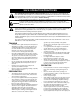
Owner’s Manual 9 Horse Power 28” Two-Stage Wheel Drive Snow Thrower Model No. 247.888530 CAUTION: Before using this product, read this manual and follow all safety rules and operating instructions. • Safety • Assembly ES • Operation • Service • Maintenance • Español Sears, Roebuck And Co., Hoffman Estates, IL 60179, U.S.A. Visit our website: www.sears.com/craftsman Printed in U.S.A.
TABLE OF CONTENTS Content Page Content Page Warranty Information .........................................2 Service & Adjustment.........................................20 Safe Operation Practices ...................................3 Off-Season Storage ...........................................25 Assembly ...........................................................6 Trouble-Shooting ...............................................26 Operation ........................................................
SAFE OPERATION PRACTICES This symbol points out important safety instructions which, if not followed, could endanger the personal safety and/or property of yourself and others. Read and follow all instructions in this manual before attempting to operate your snow thrower. Failure to comply with these instructions may result in personal injury. When you see this symbol—heed its warning. Your snow thrower was built to be operated according to the rules for safe operation in this manual.
• • • • • • • • • • hand in the discharge or collector openings. Use a stick or wooden broom handle to unclog the discharge opening. Take all possible precautions when leaving the unit unattended. Disengage the collector/impeller, stop the engine and remove the key. When cleaning, repairing, or inspecting, make certain collector/impeller and all moving parts have stopped. Disconnect spark plug wire and keep away from plug to prevent accidental starting.
HARDWARE PACK Lay the hardware pieces from the hardware pack on the figure here and you will have automatically sorted these according to the steps of the assembly procedure described later. (Only one unit of each hardware has been shown per group. The number in parenthesis indicates the total number of the hardware needed in that group.) Lock Washer (4) A E Flanged Nut (6) Hex Bolt (6) Hex Bolt (2) 1/4-20 x .75 1/4-20 Handle Tab (2) 5/16-18 x 1.75 Hex Bolt (2) Chute Flange Keeper (3) 5/16-18 x .
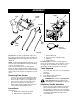
ASSEMBLY Rear Right Chute Handle Panel Left Front Handles Shift Rod Chute Crank Electric Start Cord Figure 1 IMPORTANT: This unit is shipped with engine oil in the engine, but without gasoline. After assembly, see OPERATION section of this manual for fuel selection and fill-up. NOTE: To determine right and left hand sides of your snow thrower, stand behind the unit in the operating position. See Figure 1 inset.
• Secure bottom hole in the handle to the snow thrower using 5/16 x .75" hex bolt and lock washer from the hardware pack (group A on page 5 ). Do not tighten at this time. See Figure 2. • Lock Washer & Hex Bolt (1.75”) • • Right Handle Attaching Chute Handle Tab Lock Washer & Hex Bolt (0.75”) • Place the chute assembly over the chute opening with the chute facing front of the unit. NOTE: Make sure that the chute cables are straightened while assembling the chute.
• Insert hex bolt through the upper chute crank bracket, handle panel support, and upper left handle. Secure the bracket using cupped washer and hex nut. Make sure that the cupped side of the washer is set against the handle. • • • Nut Handle Panel Support* Washer Place the other 3/8 ID flat washer (from the same group of hardware) on the end of the chute crank and insert hairpin clip into hole at the end of the chute crank. See Figure 7.
• Tighten all loose hardware on the handle assembly in the following order — first the four hex bolts at the bottom of the handle, then the carriage bolts and lastly the hex bolts on the rear of the handle panel. Attaching Shift Rod • • Place the shift lever in the sixth (6) speed. Place the bent end of the shift rod into the hole in the shift arm assembly. See Figure 11. Secure with 5/16 flat washer and hairpin clip from group D of the hardware pack.
• Place the cable barrel fitting into the hole in the trigger. You can find the triggers and associated hardware in group H of the hardware pack. See Figure 12. Trigger Cable Cable Tie Trigger Assembly Inner Cable Trigger Housing Cable Figure 14 • Barrel Fitting Slot Cable snaps in at this end Figure 12 Secure the left turn trigger cable to the lower handle using the other cable tie.
Skid Shoe The space between the shave plate and the ground can be adjusted. For close snow removal, place skid shoes in the low position. Use middle or high position when area to be cleared is uneven. NOTE: It is not recommended that you operate this snow thrower on gravel as loose gravel can be easily picked up and thrown by the auger causing an injury or damage to the snow thrower.
OPERATION Knowing Your Snow Thrower WEAR YOUR SAFETY GLASSES FORESIGHT IS BETTER THAN NO SIGHT Read this owner’s manual and safety rules before operating your snow thrower. Compare illustration below with your snow thrower to familiarize yourself with the location of various controls and adjustments. Save this manual for future reference. The operation of any snow thrower can result in foreign objects being thrown into the eyes, which can result in severe eye damage.
Operating Controls Chute Distance Control Lever (See Figure 17.) The distance that snow is thrown can be adjusted by adjusting the angle of the chute assembly. Push the chute distance control lever forward to move the upper chute down and decrease the distance. Pull the lever back toward the rear to move the upper chute up and increase the distance. Chute Crank The chute crank is located on the left hand side of the snow thrower.
To avoid engine problems, the fuel system should be emptied before storage for 30 days or longer. Drain the gas tank, start the engine and let it run until the fuel lines and carburetor are empty. Use fresh fuel next season. See storage Instructions for additional information. • Determine whether your house wiring is a threewire grounded system. Ask a licensed electrician if you are not certain.
• • • • • • • Make sure that the auger drive and the traction drive levers are in the disengaged RELEASED position. Move throttle control lever to FAST position. Remove the keys from the plastic bag. Push key into the ignition slot. Make sure it snaps into place. Do not turn key. Keep the second key in a safe place. Rotate the choke knob to FULL choke position. Connect the power cord to the switch box on the engine. Plug the other end of the power cord into a three-hole, grounded 120 volt A.C.
WARNING: To stop the auger, both levers must be released. • Discharge snow downwind whenever possible. Slightly overlap each previous swath. • Set the skid shoes 1/4" below the scraper bar for normal usage. The skid shoes may be adjusted upward for hard-packed snow. NOTE: It is not recommended that you operate this snow thrower on gravel as loose gravel can be easily picked up and thrown by the auger causing an injury or damage to the snow thrower.
MAINTENANCE General Recommendations • • Always observe safety rules when performing any maintenance. The warranty on this snow thrower does not cover items that have been subjected to operator abuse or negligence. To receive full value from the warranty, operator must maintain the snow thrower as instructed in this manual. Some adjustments will have to be made periodically to maintain your unit properly.
Lubrication Check V-belts For a view of the lubrication points on the snow thrower, see Figure 19. Follow the instructions below to check the condition of the drive belts every 50 hours of operation. • Remove the plastic belt cover on the front of the engine by removing two self-tapping screws. • Visually inspect for frayed, cracked, or excessively worn out belts. Sprocket Shaft • Lubricate the sprocket shaft with grease at least once a season or after every 25 hours of operation.
• o 32 F colder 5W30 warmer • SAE30 • Viscosity Chart NOTE: Although multi-viscosity oils (5W30, 10W30 etc.) improve starting in cold weather, these multiviscosity oils will result in increased oil consumption when used above 32oF. Check your snow thrower’s engine oil level more frequently to avoid possible engine damage from running low on oil. Refer to the viscosity chart for proper selection of engine oil. WARNING: Temperature of muffler and nearby areas may exceed 150o F(65oC).
SERVICE & ADJUSTMENTS and the drive plate in all positions of the shift lever. • With the traction drive clutch engaged, the friction wheel must contact the drive plate (shown in Figure 30). • If adjustment is necessary, loosen the jam nut on the traction drive cable and thread the cable in or out as necessary. See Figure 22. Tighten the jam nut to secure the cable when correct adjustment is reached. Reassemble the frame cover. NOTE: If you placed plastic under the gas cap, be certain to remove it.
Carburetor WARNING: If any adjustments are made to the engine while the engine is running (e.g. carburetor), keep clear of all moving parts. Be careful of heated surfaces and mufflers. • Minor carburetor adjustments may be required to compensate for differences in fuel temperature, altitude and load. bolts, belleville washers and hex nuts which attach shave plate to the snow thrower housing. For location of shave plate, see Figure 23.
• • Remove the six hex nuts and lock washers which attach the auger housing assembly to the frame assembly. See Figure 26. WARNING: Do not attempt to change the auger belt without the help of an assistant. It is very important that one person, standing at the operating position, firmly hold the snow thrower housing to prevent it from tipping while the other person replaces the belt. Failure to comply with this may result in injury. To remove the front auger drive belt, push the idler pulley to the left.
• • Changing Friction Wheel Rubber Reinstall the belt cover on front of the engine with the two self-tapping screws and flat washers. Reattach the chute crank to the chute assembly with the hairpin clip and flat washer. • • NOTE: Make sure that the auger cable is routed in front of the belt. • Drive Belt • • • • • • • • • Check drive belt every 50 hours of operation for wear and tear. Drain the gasoline from the snow thrower, or place a piece of plastic under the gas cap.
Shift Arm Assembly Shift Arm Assembly Pin Sprocket Sprocket Spacer Sprocket Spacer Spacer Hex Shaft Pin Hex Hub of Sprocket Friction Wheel Figure 33 Friction Wheel • Align the hex shaft with the right hand bearing and carefully guide the left hand bearing into the left side of the housing. • Reassemble the drive cover with the four screws that were earlier removed. Note: If you placed plastic under the gas cap, be certain to remove it.
OFF-SEASON STORAGE WARNING: Drain fuel into approved container outdoors, away from any open flame. Be certain engine is cool. Do not smoke. If the snow thrower will not be used for 30 days or longer, or at the end of the snow season when the last possibility of snow is gone, the equipment needs to be stored properly. Follow storage instructions below to ensure top performance from the snow thrower for many more years.
TROUBLE-SHOOTING Trouble Possible Cause(s) Corrective Action Engine fails to start Fuel tank empty, or stale fuel. Fill tank with clean, fresh gasoline. Fuel will not last over thirty days unless a fuel stabilizer is used. Blocked fuel line. Clean fuel line. Choke not in ON position Move switch to ON position Faulty spark plug. Clean, adjust gap or replace. Key not in switch on engine. Insert key. Connect spark plug wire. Spark plug wire disconnected. Primer button not depressed.
LABELS MAP 27
REPAIR PARTS SEARS CRAFTSMAN 9.0 H.P. SNOW THROWER MODEL 247.888530 32 34 11 7 27 26 1 29 2 4 8 22 19 16 20 20 15 15 24 20 15 12 25 30 3 20 21 6 35 9 14 18 40 26 6 43 24 17 42 24 25 12 41 15 23 31 13 36 38 39 31 23 28 10 37 NOTE: For painted parts, please refer to the list of color codes below. Please add the applicable color code, wherever needed, to the part number to order a replacement part.
SEARS CRAFTSMAN 9.0 H.P. SNOW THROWER MODEL 247.888530 Key. No. Part No. 1. 2. 3. 4. 6. 7. 8. 05931A 684-0041C 684-0065 705-5226 710-0451 710-0459A 710-0604 9. 10. 11. 12. 13. 14. 15. 16. 17. 18. 19. 20. 21. 710-0703 710-0890A 712-0116 712-0324 712-0429 712-0798 712-3010 712-3068 715-0114 731-1379B 732-0611 736-0119 736-0169 Description Key. No. Bearing Housing Auger Housing Assy. 28” Impeller Assy. 12” dia. Chute Reinforcement Carriage Bolt 5/16-18 x .75” Gr.2 Hex Screw 3/8-24 x 1.5” Gr.
SEARS CRAFTSMAN 9.0 H.P. SNOW THROWER MODEL 247.888530 NOTE: For painted parts, please refer to the list of color codes below. Please add the applicable color code, wherever needed, to the part number to order a replacement part. For instance, if a part, numbered 700-xxxx, is painted polo green, the part number to order would be 700-xxxx-0689.
SEARS CRAFTSMAN 9.0 H.P. SNOW THROWER MODEL 247.888530 Key. No. Part No. 1. 2. 3. 4. 5. 6. 7. 8. 9. 618-0043 618-0044 618-0303B 656-0012A 684-0014B 684-0042CB 784-5731A 684-0131A 710-0599 10. 710-0809 11. 710-1652 12. 13. 14. 15. 16. 17. 18. 19. 20. 21. 22. 23. 24. 25. 26. 27. 711-1267 711-1268 711-1364 712-0711 712-3017 713-0233 713-0374 713-0413 713-0472 714-0104 736-0142 714-0474 716-0102 721-0263 732-0209 732-0264 Description Key. No. 28. 29. 30. 32. 33. 34. 35. 36. 37. 38. 39. 40. 41. 42.
SEARS CRAFTSMAN 9.0 H.P. SNOW THROWER MODEL 247.
SEARS CRAFTSMAN 9.0 H.P. SNOW THROWER MODEL 247.888530 Key No. 1 2 Part No.
SEARS CRAFTSMAN 9.0 H.P. SNOW THROWER MODEL 247.888530 3 1 2 Key. No. 1. 2. 3. Part No. 712-0324 732-0705 — Key. No. 1. 2. 3. Description Hex Lock Nut: 1/4-20 Cable Guide Craftsman Engine model 143.999005 Part No. 734-1709 738-0994 714-0143 Description Wheel Assembly: 16.5 x 4.8 Steerable Axle: 0.75” dia. x 12.201” Lg.
SEARS CRAFTSMAN 9.0 H.P. SNOW THROWER MODEL 247.888530 7 IMPORTANT: For a properly working machine, use Factory Approved Parts. 10 V-Belts are specially designed to engage and disengage safely. A substitute (non-OEM) V-Belt can be dangerous by not disengaging completely. NOTE: For painted parts, please refer to the list of color codes below. Please add the applicable color code, wherever needed, to the part number to order a replacement part.
Craftsman Engine Model No. 143.999005 for Craftsman Snow Thrower Model 247.
Craftsman Engine Model No. 143.999005 for Craftsman Snow Thrower Model 247.888530 Key No. 1 2 3 4 5 15 15A 15B 16 17 18 19 20 25 26 28 30 35 36 37 38 40 40 41 41 42 42 43 45 47 48 49 50 60 65 69 70 71 75 76 80 81 82 83 84 86 87 89 90 92 Part No.
Craftsman Engine Model No. 143.999005 for Craftsman Snow Thrower Model 247.888530 Table continued from previous page Key No. Part No.
Craftsman Engine Model No. 143.999005 for Craftsman Snow Thrower Model 247.888530 CARBURETOR Key No. 0 1 2 6 7 10 14 15 16 17 18 20 20A 25 27 28 29 30 31 32 33 36 37 40 44 47 48 — 39 Part No. Description Carburetor (Incl. 184 of Engine Parts List) 631776A Throttle Shaft & Lever Ass’y. 631970 Throttle Return Spring 631778 Throttle Shutter 650506 Shutter Screw 632112 Choke Shaft & Lever Ass’y.
GARANTIA DE INFORMACIÓN Por un año desde la fecha de compra cuando este expulsor de nieve Craftsman sea mantenido, lubricado y puesto a punto de acuerdo con las instrucciones de operación y mantenimiento en el manual del proprietario, Sears reparará libre de costo cualquier defecto de material o de mano de obra. Esta garantia se aplica por 30 dias solamente a partir de la fecha de compra, si el expulsor de nieve se usa para fines comerciales o de alquiler.
PRACTICAS SEGURAS DE OPERACION Peligro: Su expulsor de nieve fue fabricada para operarse de acuerdo con las reglas para una operacion segura en este manual. Al igual que con cualquier tipo de equipo motorizado, la falta de cuidado o error de parte del operador puede resultar en lesiones graves. No observar las instrucciones siguientes de seguridad podria resultar en lesiones graves o en la muerte.
• • • • • • • • • • Después de golpear un objeto, apague el motor, extraiga el cable de la bujía, e inspeccione completamente el expulsor de nieve por averías. Antes de volver a arrancar y operar el expulsor de nieve, repare las averías. Si el expulsor de nieve comienza a vibrar anormalmente, apague el motor e inspeccione inmediatamente por la causa. La vibración es generalmente una advertencia de problemas.
CONJUNTO DE FERRETERIA DE FERRETERIA Despliegue la ferretería de acuerdo con la ilustración para fines de identificación. Las piezas están ilustradas a la mitad de su tamaño aproximadamente. Los números de pieza se muestran entre paréntesis. (El conjunto de ferretería puede contener artículos adicionales que no se usan en su unidad.) Arandela de seguridad (4) A E Tuerca con reborde (6) Perno hexagonal (6) Perno hexagonal (2) 1/4-20 x .75 1/4-20 Aleta del mango (2) 5/16-18 x 1.
ENSAMBLADO Canaleta Parte posterior Parte derecha Panel de Mango Parte delantera Parte izquierda Mangos Vara de cambios Manivela de la canaleta Conjunto de ferreteria Figura 1 Sugerencias de ensamblado: Para facilitar el ensamblado, extraiga la canaleta de la caja y colóquela sobre el motor. No desenvuelva la canaleta hasta después de instalar el panel del mango, los cables del embrague y la cubierta de la correa.
• conjunto de la ferretería (Grupo C en la página 6). Vea la Figura 3. No ajuste en este momento. Ajuste toda la ferretería floja en el conjunto del mango en el siguiente orden-primero los pernos hexagonales al fondo del mango, a continuación los pernos del carro y finalmente los pernos hexagonales en el reverso del panel del mango. Fijacion De La Canaleta • Mango derecho Aleta del mango Nota: Asegúrese que los cables de la canaleta estén rectos mientras ensambla la canaleta.
• hexagonal. Asegúrese que el lado acopado de la arandela está colocado contra el contorno de la manija. Ajuste el soporte de la canaleta de manera que la espiral en la manija de la canaleta se enganche completamente con los dientes del conjunto de la canaleta. Ajuste bien las tuercas en el soporte inferior de la manija de la canaleta.
• Deslice los cables que se extienden desde el panel del mango a la canaleta dentro de la guía de cable ubicada al tope del motor. Vea la Figura 9. • Guía de Cable Usted alcanzará un ajuste correcto cuando haya un exceso mínimo en el cable pero no está ajustado. Sujete las áreas planas del casquillo con pinzas y ajuste la contratuerca contra el casquillo. PRECAUCION: Los cables se aflojarán si usted no ajusta la contratuerca.
• Una vez que el casquillo se deslice dentro del orificio, gírelo en sentido contrario a las agujas del reloj una vuelta completa e inserte en el orificio en la palanca de cambios. Asegure con el tornillo Tuerca soldada Nota: Puede ser necesario mover la palanca de cambios fuera de la posición de sexta velocidad y moverla hacia la posición de quinta velocidad hasta que el casquillo se deslice dentro del orificio sin fuerza.
IMPORTANTE: Ensamble su expulsor de nieve, a continuación inspeccione los ajustes según las instrucciones y efectúe los ajustes finales necesarios antes de operar la unidad. El no seguir las instrucciones puede causar averías al expulsor de nieve. Ajustes Finales Ajuste del Control de la Hélice • • • • Para inspeccionar el ajuste del control de la hélice, empuje hacia adelante sobre la empuñadura izquierda del embrague hasta que esté comprimido el amortiguador de goma.
OPERACION ANTES DE HACER FUNCIONAR SU EXPULSOR DE NIEVE LEA ESTE MANUAL DEL PROPIETARIO Compare las ilustraciones en este figura 17 con su expulsor de nieve para familiarizarse con la ubicación de varios controles y ajustes. Guarde este manual para referencia futura. La operación de un expulsor de nieve puede resultar en objetos despedidos contra los ojos, lo que puede resultar en lesiones graves de los ojos.
Propulsor De Traccion/Seguro Del Embrague De La Espiral Sin Fin ADVERTENCIA: Nunca llene el tanque bajo techo, con el motor funcionando o mientras el motor está caliente. No fume al llenar el tanque de combustible. El embrague del propulsor de tracción está ubicado en el mango derecho. Accione el embrague del propulsor de tracción para enganchar la rueda motriz. Suelte para parar.
Como Apagar El Motor • • Gire la perilla del regulador a la posición OFF. Oprima el botón del cebador mientras cubre el orificio de ventilación. Saque el dedo del cebador entre cebados. No cebe para arrancar un motor caliente. Si la temperatura es mayor de 15 grados F cebe dos o tres veces y cuatro veces si es menor de 15 grados F. • Conecte el cordón de potencia a la caja del interruptor en el motor.
Manejo De La Limpiadora De Nieve • Las palancas de los gatillos están ubicadas en la parte inferior de los mangos y se usan para manejar su limpiadora de nieve. Consejos De Operacion Nota: El embrague del propulsor debe estar enganchado al usar los gatillos para manejar la limpiadora de nieve. Nota: Dado que el motor no desarrollará su potencia plena hasta que alcance la temperatura de operación, permita que el motor se caliente por unos pocos minutos.
MANTENIMIENTO ADVERTENCIA: Antes de efectuar cualquier ajuste o reparación, siempre apague el motor, desconecte el cable de la bujía y aléjelo de la bujía. Recomendaciones Generales • Observe siempre las reglas de seguridad al efectuar el mantenimiento. La garantía en este expulsor de nieve no cubre artículos que han estado sujetos a abuso o negligencia por el operador. El operador debe mantener el expulsor de nieve según las instrucciones de este manual, para recibir el valor completo de la garantía.
Propulsor De Traccion/Control Del Propulsor De Traccion • Para una selección adecuada del aceite del motor, refiérase a la tabla de viscosidad. El aceite debe estar en la marca FULL de la varilla medidora, con el motor sobre un suelo nivelado. Lubrique las levas en los extremos de las varas de control que bloquean entre sí los controles del propulsor de tracción y de la hélice una vez por temporada por lo menos o cada veinticinco horas de funcionamiento con grasa.
SERVICE & AJUSTES ADVERTENCIA: Antes de efectuar cualquier ajuste o reparación, siempre apague el motor, desconecte el cable de la bujía y aléjelo de la bujía.Mientras el motor está funcionando, nunca trate de limpiar la canaleta ni efectuar ajustes. Nota: Recuerde de extraer la tela plástica si la colocó debajo de la tapa de gasolina. Vara De Cambios Ajustes Zapata Deslizante Puede ajustarse el espacio entre la plancha raspadora y el suelo.
Service • Helices Las hélices están aseguradas al eje de la espiral mediante dos pernos de corte y contratuercas hexagonales. Si usted golpea un objeto extraño o se atasca con hielo, el expulsor de nieve está diseñado de manera que los pernos hexagonales se cortarán. Vea la Figura 22. • Si las hélices no giran, inspeccione para verificar si los pernos se han cortado. • Reemplace si fuera necesario. Se han provisto dos pernos hexagonales y contratuercas hexagonales de repuesto con el expulsor de nieve.
ADVERTENCIA: No intente cambiar la correa de la espiral sin fin sin la ayuda de un asistente. Es muy importante que una persona, parada en la posición operativa, sujete firmemente el bastidor de la limpiadora de nieve para evitar que vuelque mientras que la otra persona reemplaza la correa. El no hacerlo así puede resultar en lesiones.
• Vuelva a fijar la manija de la canaleta al conjunto de la canaleta con el broche de cabello y la arandela plana. Rueda de friccion Rueda de fricción Nota: Asegúrese que el cable de la espiral sin fin esté encaminado al frente de la correa. Correa propulsora • • • • Drene la gasolina de la limpiadora de nieve o coloque un trozo de plástico debajo de la tapa de gasolina. Extraiga la cubierta plástica de la correa al frente del motor extrayendo los dos tornillos autoroscantes.
• • • • Sujetando el conjunto de la rueda de fricción, deslice el eje hexagonal fuera del lado izquierdo de la unidad. Caerá el separador del lado derecho del eje hexagonal y el piñon deberá colgar suelto en la cadena. Levante el conjunto de la rueda de fricción entre el eje y los conjuntos del eje propulsor. Extraiga los seis tornillos de ambos lados del conjunto de la rueda. Extraiga la goma de la rueda de fricción de entre la plancha de la rueda de fricción.
ALMACENAMIENTO DE FUERA DE TEMPORADA Preparación del motor Si la unidad va a almacenarse por más de 30 días, prepare para almacenamiento como sigue: Es importante evitar que se formen depósitos de goma en las partes esenciales del sistema de combustible del motor tales como el carburador, filtro de combustible, manguera de combustible o tanque durante el almacenamiento.
TABLA DE LOCALIZACION DE FALLAS Problema Causa(s) posible Accion correctora El motor funciona errático Unidad funcionando en CHOKE (REGULADOR) Tuberia de gasolina bloqueada o combustible rancio. Agua o suciedad en el sistema de combustible. Carburador mal ajustado. Pérdida de potencia Cable de la bujía flojo. Orificio de ventilación de la tapa de gasolina taponado. Orificio de escape taponado. El carburador no está bien ajustado.
Your Notes/Vuestro Apuntes 63
In U.S.A. or Canada for in-home major brand repair service: Call 24 hours a day, 7 days a week 1-800-4-MY-HOMESM (1-800-469-4663) Para pedir servicio de reparación a domicillio — 1-800-676-5811 Au Canada pour tout le service ou les pièces — 1-800-469-4663 For the repair or replacement parts you need: Call 6 a.m. — 11 p.m.