® Caution: ReadandFollow All SafetyRules andInstructions BeforeOperating ThisEquipment 5 HORSEPOWER 3 CUTTnNG STAGE MULCHING AND BAGGING CHiPPER-SHREDDER Assembly Operation CustomerResponsibilities Serviceand Adjustment RepairParts SEARS,ROEBUCK ANDCO.,HoffmanEstates,iL 60195U.S.A. Printed in U.S.A.
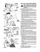
SAFETY RULES WARNING: TO REDUCE SAFETY INSTRUCTIONS. PERSONAL INJURY. THE POTENTIAL FOR ANY INJURY, FAILURE TO COMPLY WITH THE TRAINING e Read this owner's manual carefully in its entirety before attempting to assemble or operate this machine+ Be com+ pletety familiar with the controls and the proper use of this machine before operating it+ Keep this manual in a safe place for future and regular reference and for ordering replacement parts.
CONGRATULATIONS on your purchase of a Sears Craftsman Chipper-Shredder,, It has been designed, engineered and manufactured to give you the best possible dependability and performance_ Should you experience any problem you cannot easily remedy, please contact your nearest Sears Service Center/ Department in the United States.
iii i, i,ii i ,UU,lU,i i TABLE OF CONTENTS ,,u, STORAGE ................................................................................... 13 SERVICE AND ADJUSTMENT ..................................... 13-!5 TROUBLE SHOOTING ..................................................... 16 REPAIR PARTS--CHIPPER-SHREDDER ........ 17, 18 REPAIR PARTS--ENGINE ....................................... 19-23 PARTS ORDERING/SERVICE .....................................16 i i,,i lUl INDEX i ii,u , u, A 0 Oil ..
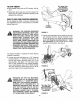
ASSEMBLY = £ INSTRUCTIONS i i1,1111,1,1,111,1iii iiiii1,111111[111111111111111111111111111111111 IMPORTANT: This unit is shipped WITHOUT GASOLINE or OIL, After assembly, see operation section of this manuat for proper fuel and engine oil recommendations 3 Flat ""__ Washer | _ 5/16 LD.
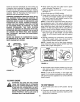
HOWTO SET-UPYOUR CHIPPER-SHREDDER Housing MAKE CERTAIN THE SPARK PLUG Bolt AWAY THE SPARK PLUG WIRE IS FROM DISCONNECTED AND MOVED BEFORE ASSEMBLING THE CHIPPER,_ SHREDDER. Chute Hex Nut . Hand Knob _ / FIGURE2. .._\ / Stop Washer Upper Guide FIGURE 3. Hopper Pivot Door, ASSEMBLE THIS TRUSS SCREW AND NUT FIRST Leaf Ramp Section Remove Truss Screw and Nut Assembly FIGURE 4_ Drawstring get FIGURE 5.
string,andputtonthedrawstringuntiltile bagis tight aroundthechuteopening.. Releaseplungerto lockit intopositionSeefigure5. ® To attachthe bag,placethe openingof the bag overthechutedeflectorso it completely coversthe chuteopeningDepressthe plungeron thedraw................................... ii, i ,lllllll,lll ,IIIIHIIII OPERATION i iii ii ii ,i ii ,i KNOW YOUR CHIPPER-SHREDDER READ THIS OWNER'S MANUAL AND SAFETY RULES BEFORE OPERATING YOUR CHIPPER-SHREDDER.
TO STOP EHGIHE No Larger Than 1/2" Diameter Recommended) Or 1" Diameter (Maximum) ® Move throttle control lever to OFF position. See figure6° ® Disconnect spark plug wire and move away from spark plug to prevent accidental starting while equipment is unattended_ HOW TO USE YOUR CHIPPER-SHREDDER Do not attempt to shred or chip any materiat other than vegetation found in a normal yard (Leo, branches, leaves, twigs, etc_)+ \ Hopper Assembly WARNING: THE CHIPPER-SHREDDER DISCHARGES MATERIALS WITH CONSIDERA
e To lower the hopper assembly, use one hand to grasp the handle at the top of the hopper assembly and lift slightly Pull up on the release bar, and lower the hopper' assembly to the ground.. Release the bar. See figure t0. Hopper Assembly GASAND OIL FILL-UP OIL Only use high quality detergent oil rated with API setvice classification SG. Select the oil's viscosity grade according to your expected operating temperature. Colder -,_ 32°F 5W30 Bar FIGURE 10.
Check the fuel level periodically to avoid running out of gasoline while operating the chipper-shredder. If the unit runs out of gas as it is shredding or chipping, it may be necessary to unclog the unit before it can be restarted.. Refer to "Removing the Flail Screen" in SERVICE AND ADJUSTMENT section_ WARNING: EXPERIENCE ® Attach spark plug wire and rubber boot to spark plug if necessary. See figure 13. ® Place the throttle control lever in FAST position_ See figure 14..
IIIINIIIIIlUlIIIlUlU lUllU II IllUU ' II " II II U II II I' " II I' III I' I CUSTOMER RESPONSIBILHTHES 1,1,11,1 M iiii MAINTENANCE SCHEDULE FILL IN DATES AS YOU COMPLETE REGULAR SERVICE ,ul i,i, I-- o Oil Pivot Points O rr Clean Shredder ",J .,/ _/ a.
AIR CLEANER WARNING: PERIODICALLY CLEAN MUFFLER AREA TO REMOVE ALL GRASS, DIRT AND COMBUSTIBLE DEBRIS. The air cleaner prevents damaging dirt, dust, etc. from entering the carburetor and being forced into the engine and is important to engine life and performanceo Never run your engine without pletely assembled. air cleaner com- CLEANING e The chipper-shredder may be cleaned by running water from a hose through the hopper assembly and chipper chute with the engine running.
u =, in u l STORAGE e Drain the fuel tank, Prepare your chipper-shredder for' storage at the end of the season or if the unit will not be used for 30 days or more,, ® Start the engine and let it run until the fuel lines and carburetor are empty e Never use engine or carburetor cleaner products in the fuel tank or permanent damage may occur, e Use fresh fuel next season WITH FUEL IN THE FUEL TANK INSIDE WARNING: NEVER STORE MACHINE OF BUILDING WHERE FUMES MAY REACH AN OPEN FLAME OR SPARK, OR WHERE IGNIT
Chute Replace or sharpen blades. If sharpening, make certain to remove an equal amount from each blade Reassemble in reverse order. Hairpin \ Clips, Clevis Pins _-_Hex Nuts. Washers 4 Make certain blades are reassembled with the sharp edge facing the direction shown in figure 19 (sharp edge is assembled toward the slotted opening in the impeller assembly). SHREDDING BLADE The shredding blade may be removed for sharpening or replacement as follows.
NOTE:Usecautionwhenremovingthebladeto avoid contactingtheweldboltsonthehousing. ® Whensharpeningthe blade, followthe original angleof grindas a guide.It is extremelyimportant thateachcuttingedgereceivesanequalamountof grindingtopreventanunbalanced blade.Anunbalancedbladewill causeexcessivevibrationwhen rotatingat highspeedsandmaycausedamageto theunit e The blade can be tested for balance by balancing it on a round shaft screwdriver or nail.
TROUBLE SHOOTING PROBLEM CORRECTIVE ACTION Engine faits to start e Fuel tank empty, or stale fuel, ® Spark plug wire disconnected. • Faulty spark plug. • Fill tank with clean, fresh fuel e Connect wire to spark plug. e Clean, adjust gap or replace. Loss of power; operation erratic e Spark plug wire loose. • Unit running on CHOKE. ® Blocked fuel line or stale fuel • Connect and tighten spark plug wire e Move choke lever to OFF position.
SEARS CRAFTSMAN 5 H.P. CHIPPER-SHREDDER MODEL NOS. 247.797854 Repair Parts 247.
SEARS CRAFTSMAN 5 H.P. CHIPPER-SHREDDER MODEL NOS. 247.797854 Repair Parts KEY NOo 1 2 PART NOo DESCRIPTION 742-057I 710-0818 Blade Hex Patch Bolt 3/8-24 x 2" Lg_ (Gro 8) (247.797854) Hex Patch Bolt 3/8-24 x 2,25" Lg, (247.797855) Sq. Key 1/4 x 2°0" Lg° (247°797854) L-Wash, 3/8" I.D HoD. FI-Wash. ,,406" LD, x 1,25" O.D, Hdno Flail Flail Spacer Clevis Pin °496" Dia. Flail Spacer w/. 160" Diao Hole Spring Roll Pin I.12" Lg. FI-Washo o531" I.D. x .
BRIGGS AND STRATTON 5 H.P. ENGINE MODEL NOS. 135212-0272-01 Repai r Parts REFo NOo PART NO, 55 56 57 58 494846 493824 262594 280406 59 60 65 69 69A 373 456 459 461 515 608 1016 396892 393152 94686 280973 224322 92987 224321 492833 262626 262625 495766 224278 135212-0140-01 373 DESCRIPTION Housing-Rewind Starter Pulley-Rewind Starter Spring-Rewind Starter Rope-Rewind Starter Cut to Required Length Insert-Starter Handle Handle-Rewind Starter Screw-Housing Mtg.
BRIGGS AND STRATTON 5 H.P. ENGINE MODEL Repair Parts NOS.
BRIGGS AND STRATTON 5 H.P. ENGINE MODEL NOS. 135212-0272-01 Repai r Parts REFo NO, 12 18 19 20 21 22 25 26 27 28 29 30 32 45 46 219 220 227 230 562 592 614 615 616 REE NO, PART NO,, *270080 *270125 *270126 493916 495660 *298504 66768 94682 298904 298905 298906 298907 298982 298983 298984 298985 26026 298909 298908 299430 221890 94745 260642 212733 494845 221551 490374 222450 92613 231082 93306 93307 231077 PART' NO. 135212-0140-01 27 DESCRIPTI Gasket-Crankcase (.015" Thick, Std.
BRIGGS AND STRATrON 5 H.P. ENGINE MODEL Repair Parts REF. NO.