Operator’s Manual R1500 SERIES LAWN TRACTORS Model Nos. 247.29900* & 247.26900* * -- Last digit of model number varies 5 6 Safe Operation Practices..................................................2 Slope Gauge....................................................................7 Assembly & Set-Up...........................................................8 Controls & Operation...................................................... 14 Service & Maintenance...................................................
SAFETY INSTRUCTIONS WARNING DANGER This symbol points out important safety instructions which, if not followed, could endanger the personal safety and/or property of yourself and others. Read and follow all instructions in this manual before attempting to operate this machine. Failure to comply with these instructions may result in personal injury. When you see this symbol, HEED ITS WARNING! This machine was built to be operated according to the safe operation practices in this manual.
SAFETY INSTRUCTIONS • Check overhead clearances carefully before driving under low hanging tree branches, wires, door openings etc., where the operator may be struck or pulled from the machine, which could result in serious injury. Do Not: • Do not turn on slopes unless necessary; then, turn slowly and gradually downhill, if possible. • Disengage all attachment clutches and depress the brake pedal completely before attempting to start engine.
SAFETY INSTRUCTIONS • Always use extra caution when towing with a machine capable of making tight turns (e.g. “zero-turn” ride-on mower). Make wide turns to avoid jack-knifing. • Travel slowly and allow extra distance to stop. • Do not coast downhill. • Check brake operation frequently as it is subjected to wear during normal operation. Adjust and service as required. • Check the blade(s) and engine mounting bolts at frequent intervals for proper tightness.
SAFETY INSTRUCTIONS NOTICE REGARDING EMISSIONS SPARK ARRESTOR Engines which are certified to comply with California and federal EPA emission regulations for SORE (Small Off Road Equipment) are certified to operate on regular unleaded gasoline, and may include the following emission control systems: Engine Modification (EM), Oxidizing Catalyst (OC), Secondary Air Injection (SAI) and Three Way Catalyst (TWC) if so equipped.
SAFETY INSTRUCTIONS Symbol Description BYSTANDERS Keep bystanders, helpers, children and pets at least 75 feet from the machine while it is in operation. WARNING— SLOPE OPERATION Do not operate this machine on a slope greater than 12 degrees. WARNING— HOT SURFACE Engine parts, especially the muffler, become extremely hot during operation. Allow engine and muffler to cool before touching. DANGER — ROTATING BLADES To reduce the risk of injury, keep hands and feet away.
SLOPE GAUGE (OK) Figure 1 12° Slope 12 ° d a s hed line USE THIS SLOPE GAUGE TO DETERMINE IF A SLOPE IS TOO STEEP FOR SAFE OPERATION! To check the slope, proceed as follows: 1. Remove this page and fold along the dashed line. 2. Locate a vertical object on or behind the slope (e.g. a pole, building, fence, tree, etc.) 3. Align either side of the slope gauge with the object (See Figure 1 and Figure 2 ). 4. Adjust gauge up or down until the left corner touches the slope (See Figure 1 and Figure 2). 5.
ASSEMBLY Contents of Crate • One Riding Mower • One Seat Assembly • One Discharge Chute Assembly • One Steering Wheel/Shaft Assembly • One Rear Engine Cover • One Hardware Pack • One Rear Hitch Plate • One Oil Drain Sleeve • One Riding Mower Operator’s Manual • One Steering Pedestal Cap Contents of Hardware Pack 4. Before beginning installation, remove all the contents from the crate and all the hardware from the pack to make sure everything is present.
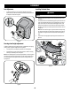
ASSEMBLY Attaching The Seat 4. If the seat for your tractor was not attached at the factory, follow the applicable instructions below to attach it. 1. Using a 1/4-inch drive ratchet with a 3/8” socket, secure the seat bracket with the self-tapping screws removed in Step 2. See Figure 6. Remove the shoulder bolts and lock nuts from the seat mounting bracket included in your hardware pack. See Figure 4. Figure 4 2. Remove the two self-tapping screws factory installed on the tractor. See Figure 5.
ASSEMBLY Seat Adjustment 1. Installing The Deck Chute To adjust the position of the seat, remove the adjustment knob on the bottom of the seat. Slide the seat forward or backward as desired. Reinstall the adjustment knob. Refer to Figure 8. WARNING NEVER operate this tractor without either the mulch plug or deck chute installed. 1. Remove the wing knobs installed on the mowing deck and retain for later installation. 2. Install the deck chute into the deck discharge opening on the deck.
ASSEMBLY Install The Rear Engine Cover Installing the Hitch Plate 1. Remove the two factory installed hex screws located on the rear engine cover mounting bracket. Retain the screws for later instructions. See Figure 11. 1. 2. Install the rear engine cover by positioning it in place as shown in Figure 11. Tip the engine cover forward to fit it into the slots provided, then rotate it backwards to align the mounting holes. Slide the hitch plate in between the frame and the rear cover on your rider.
ASSEMBLY 3. 4. Remove the plastic cover, if present, from the negative battery terminal and attach the black cable to the negative battery terminal (–) with the remaining hex bolt and hex nut, using a 7/16 inch wrench and socket wrench. See Figure 14. NOTE: A 5w30 synthetic oil may be used to improve start ability for cold weather (temperatures below 40 F). Position the red rubber boot over the positive battery terminal to help protect it from corrosion.
ASSEMBLY Adding Fuel Fuel Requirements CAUTION WARNING Operating the engine with E85 fuel, an oil/gasoline mixture, dirty gasoline, or gasoline over 30 days old without fuel stabilizing additive may result in damage to your engine’s carburetor. Subsequent damage would not be covered under the Craftsman warranty. Use automotive gasoline (unleaded or low leaded to minimize combustion chamber deposits) with a minimum of 87 octane.
OPERATION Clutch/Brake Pedal Speed Control & Parking Brake Lever Fuel Level Indicator Ignition Switch Shift Lever Fuel Fill Cap Throttle/Choke Lever Deck Lift Lever Cup Holder Oil Fill Cap PTO (Blade Engage) Lever Figure 17 NOTE: Any reference in this manual to the RIGHT or LEFT side of the tractor is observed from operator’s seat position facing forward towards the front of tractor.
OPERATION Throttle / Choke Control Shift Lever The throttle control lever is located on the left fender of the tractor as seen from the operator’s position, see Figure 17. This lever controls the speed of the engine, as well as the choke when it is pushed all the way forward. When set in a given position, the throttle will maintain a uniform engine speed. The shift lever is located on the control panel just below the seat, in the center of the tractor.
OPERATION Safety Interlock Switches The safety interlock system is designed for safe operation of the tractor. If this system should ever malfunction, do not operate the tractor. Immediately contact 1-888-331-4569 to have the system serviced. • The safety interlock system prevents the engine from starting unless the parking brake is engaged and the PTO (Blade Engage) lever is in the disengaged (OFF) position.
OPERATION Starting the Engine WARNING Avoid Serious Injury or Death • Know location and function of all controls. • Remove objects which could be thrown by the blades. • Go up and down slopes, not across. • Use extra caution on slopes. Do not mow slopes greater than 12 degrees. Avoid sudden turns. Use low speed. WARNING Do not operate the tractor if the interlock system is malfunctioning. This system was designed for your safety and protection.
OPERATION Driving The Tractor WARNING Avoid sudden starts, excessive speed and sudden stops. WARNING Do not leave the seat of the tractor without first placing the PTO (Blade Engage) lever in the disengaged (OFF) position, depressing the brake pedal and engaging the parking brake. If leaving the tractor unattended, also turn the ignition key off and remove the key. 5. Depress clutch-brake pedal. 6. Place speed control lever in desired position. 7.
OPERATION Engaging the Blades Mowing Engaging the PTO (Blade Engage) transfers power to the cutting deck. To engage the blades, proceed as follows: 1. Move the throttle/choke control lever to the FAST (rabbit) position. 2. Grasp the PTO (Blade Engage) lever and pivot it all the way forward into the engaged (ON) position. 3. Keep the throttle lever in the FAST (rabbit) position for the most efficient use of the cutting deck.
SERVICE AND MAINTENANCE MAINTENANCE SCHEDULE WARNING Before performing any type of maintenance/service, disengage all controls and stop the engine. Wait until all moving parts have come to a complete stop. Disconnect spark plug wire and ground it against the engine to prevent unintended starting. Always wear safety glasses during operation or while performing any adjustments or repairs. Interval Before Each Use Follow the maintenance schedule given below. This chart describes service guidelines only.
SERVICE AND MAINTENANCE Engine Maintenance WARNING Shut off the engine before performing any maintenance. To prevent accidental start-up, disconnect the spark plug boot. 10. Start the engine. Allow it to run for a few seconds and then shut down the engine. 11. Check the oil level. IMPORTANT: Used motor oil may cause skin cancer if repeatedly left in contact with the skin for prolonged periods.
SERVICE AND MAINTENANCE Air Filter Service Paper filters cannot be cleaned and should be replaced every 100 operating hours; more often if used in extremely dusty conditions. WARNING Never use gasoline or low flash point solvents for cleaning the air filter element. A fire or explosion could result. CAUTION Do not use pressurized air or solvents to clean the air cleaner cartridge. WARNING If filters, or covers are not installed correctly serious injury or death could result from backfire.
SERVICE AND MAINTENANCE 2. Remove thumb screw (A). See Figure 26. A B Intake Manifold Figure 28 7. Figure 26 3. Pull up and remove air filter and base seal (B). See Figure 26. 4. Remove the foam pre-filter from around the paper air filter. See Figure 27. Replace paper element when dirty or damaged. Clean foam element or replace when damaged. Attach the air filter cover, making sure to align plastic rib features on the shroud to the plastic features on the air filter cover. See Figure 29.
SERVICE AND MAINTENANCE Fuel Filter Service WARNING WARNING If the engine has been running, the muffler will be very hot. Be careful not to touch the muffler. Spark Plug Spark Plug Boot Figure 30 2. 3. Visually inspect the spark plug. Discard the spark plug if there is apparent wear, or if the insulator is cracked or chipped. Clean the spark plug with a wire brush if it is to be reused. Gasoline and its vapors are extremely flammable and explosive.
SERVICE AND MAINTENANCE Fuel Filter Tab Fuel Line Clamp Figure 33 Figure 32 4. Clean Engine Remove the bow-tie cotter pin and flat washer from the deck lift assembly, and retain for reinstallation later. See Figure 34. If the engine has been running, allow it to cool for at least half an hour before cleaning. Periodically remove dirt build-up from engine. Clean the engine cooling fins every 25 hours. Clean with a brush or compressed air.
SERVICE AND MAINTENANCE 5. Remove the remaining bow-tie cotter pins securing the deck to the unit, as shown in Figure 35. 1. It is easiest to change the deck belt by first removing the cutting deck as instructed earlier in this section. Skip this step if deciding to change the deck belt with the mowing deck still installed on the unit. Otherwise, remove the cutting deck now. 2.
SERVICE AND MAINTENANCE 8. Feed the deck belt through the belt keeper bracket and work it around and onto the PTO drive pulley as shown in Figure 33. Tires WARNING Never exceed the maximum inflation pressure shown on the sidewall of tire. The recommended operating tire pressure is: • Approximately 10 psi for the rear tires • Approximately 14 psi for the front tires IMPORTANT: Refer to the tire sidewall for exact tire manufacturer’s recommended or maximum psi. Do not overinflate.
SERVICE AND MAINTENANCE Adjustments Parking Brake Adjustment WARNING WARNING Never attempt to adjust the brakes while the engine is running. Always disengage PTO (Blade Engage Lever), move shift lever into neutral position, stop engine and remove key to prevent unintended starting. Never attempt to make any adjustments while the engine is running, except where specified in the operator’s manual. Leveling the Deck NOTE: Check the tractor’s tire pressure before performing any deck leveling adjustments.
SERVICE AND MAINTENANCE The battery is sealed and is maintenance-free. Acid levels cannot be checked. Battery Failures • Always keep the battery cables and terminals clean and free of corrosive build-up. Some common causes for battery failure are: • After cleaning the battery and terminals, apply a light coat of petroleum jelly or grease to both terminals. • Incorrect initial activation • Overcharging • Always keep the rubber boot positioned over the positive terminal to prevent shorting.
SERVICE AND MAINTENANCE Fuse Deck Wash System One 15 AMP fuse is installed in your tractor’s wiring harness to protect the tractor’s electrical system from damage caused by excessive amperage. If the electrical system does not function, or your tractor’s engine will not crank; first check to be certain that the fuse has not blown. It can be found under the fender on the left side of the unit, on the wiring harness just above the battery.
OFF-SEASON STORAGE WARNING Never store lawn tractor with fuel in tank indoors or in poorly ventilated areas where fuel fumes may reach an open flame, spark, or pilot light as on a furnace, water heater, clothes dryer, or gas appliance. PREPARING THE ENGINE WARNING Gasoline is a toxic substance. Dispose of gasoline properly. Contact your local authorities for approved disposal methods. IMPORTANT: Fuel left in the fuel tank during warm weather deteriorates and will cause serious starting problems.
TROUBLESHOOTING Problem Engine fails to start Cause 1. 2. 3. 4. PTO/Blade Engage lever engaged. Parking brake not engaged. Spark plug wire(s) disconnected. Throttle/Choke control lever not in correct starting position. 5. Choke not activated 6. 7. 8. 9. 10. 11. Engine runs erratically Remedy Fuel tank empty, or stale fuel. Blocked fuel line. Faulty spark plug(s). Engine flooded. Blown Fuse(s). Safety switch(s) not properly engaged. 1. Unit running with CHOKE activated. 2.
Manual del Operador SERIE R1500 TRACTORES CORTACÉSPED Modelo Nos. 247.29900* & 247.26900* * -- El último dígito del número de modelo varía Medidas de Seguridad..............................................................2 Indicador de pendientes......................................................... 7 Armado e Instalación...............................................................8 Controles y Funcionamiento...................................................14 Servicio y Mantenimiento..............
INSTRUCCIONES DE SEGURIDAD ADVERTENCIA PELIGRO La presencia de este símbolo indica que se trata de instrucciones importantes de seguridad que se deben respetar para evitar poner en peligro su seguridad personal y/o material y la de otras personas. Lea y siga todas las instrucciones de este manual antes de poner en funcionamiento esta máquina. Si no respeta estas instrucciones podría provocar lesiones personales.
INSTRUCCIONES DE SEGURIDAD • Desenganche la(s) cuchilla(s), coloque el freno de estacionamiento, detenga el motor y espere hasta que la(s) cuchilla(s) se detenga(n) por completo antes de retirar el colector de césped, vaciar los recortes, destapar el canal, retirar restos de césped o desechos, o hacer cualquier ajuste. • Nunca deje la máquina en funcionamiento sin vigilancia. Apague siempre las cuchillas, coloque el freno de mano, detenga el motor y retire la llave antes de bajarse del vehículo.
INSTRUCCIONES DE SEGURIDAD • • Tenga extrema precaución cuando se aproxime a esquinas ciegas, portales, arbustos, árboles u otros objetos que puedan impedirle ver a un niño que se cruce en el recorrido de la máquina. Para evitar accidentes al operar en marcha atrás, siempre desenganche las cuchillas antes de colocar marcha atrás.
INSTRUCCIONES DE SEGURIDAD • Nunca altere el sistema de enclavamiento de seguridad ni otros mecanismos de seguridad. Controle periódicamente que funcionen correctamente. • Después de golpear con algún objeto extraño, detenga el motor, desconecte el cable de la bujía y conecte el motor a masa. Inspeccione minuciosamente la máquina para ver si está dañada. Repare el daño antes de arrancar y utilizar la máquina.
INSTRUCCIONES DE SEGURIDAD Symbol Description PELIGRO— DÉ EL CORTE DE PIE Guarde manos y pies lejos de hacer girar partes. PELIGRO— DÉ EL CORTE DE PIE Retroceda lentamente. Siempre mire hacia abajo y hacia atrás antes y mientras retrocede, para evitar accidentes. PELIGRO— ESCOMBROS LANZADOS Quite objetos que pueden ser lanzados por la lámina en cualquier dirección. Lleve gafas de seguridad.. PELIGRO— ESCOMBROS LANZADOS Quite objetos que pueden ser lanzados por la lámina en cualquier dirección.
PENDIENTE DE CALIBRE (ACEPTAR) Figura 1 12° lí 12° Pendiente Figura 2 12° Pendiente (DEMASIADO ESCARPADO) ua nea d i s c o ntin USO DE ESTE PENDIENTE DE CALIBRE PARA DETERMINAR SI UNA PENDIENTE ES DEMASIADO ESCARPADO PARA UNA OPERACIÓN SEGURA! Para comprobar la pendiente, haga lo siguiente: 1. Borrar esta página y doble a lo largo de la línea discontinua. 2. Localizar un objeto vertical sobre o detrás de la pendiente (un poste, un edificio, una valla, un árbol, etc.) 3.
MONTAJE Contenido del cajón • Un tractor cortacésped • Un conjunto de asiento • Un conjunto de canal de descarga • Un conjunto de rueda/eje de dirección • Una tapa trasera del motor • Un paquete de elementos de ferretería • Una placa de enganche trasera • Una manga para drenado de aceite • Un manual del operador del tractor cortacésped • Una tapa de pedestal de dirección Contenido del paquete de elementos de ferretería 4.
MONTAJE Instalación del asiento 4. Si su tractor no traía el asiento instalado de fábrica, siga las instrucciones correspondientes que se incluyen a continuación para instalarlo. 1. Con una llave de trinquete de 1/4 de pulgada y una llave de cubo de 3/8”, sujete el soporte del asiento con los tornillos autorroscantes que extrajo en el Paso 2. Vea la figura 6.
MONTAJE Ajuste del asiento 1. Instalación del canal de la plataforma Para ajustar la posición del asiento, retire las dos perillas de ajuste que están ubicadas en la parte inferior del asiento. Deslice el asiento hacia adelante o hacia atrás, según lo desee. Vuelva a colocar la perilla de ajuste. Consulte la Figura 8. ADVERTENCIA NUNCA opere este tractor si no tiene colocados el tapón de abono o el canal de la plataforma. 1.
MONTAJE Coloque la tapa trasera del motor Instalación de la placa de enganche 1. Extraiga los dos tornillos hexagonales instalados en fábrica ubicados en la ménsula de montaje de la tapa trasera del motor. Guarde los tornillos para uso posterior. Vea la Figura 11. 1. 2. Coloque la tapa trasera del motor ubicándola en su lugar como se indica en la Figura 11.
MONTAJE 4. Coloque el capuchón de goma rojo por encima del borne positivo de la batería para protegerlo contra la corrosión. NOTA: Si la batería se pone en servicio después de la fecha indicada en su parte superior o al costado de la misma, cárguela siguiendo las instrucciones de la sección Mantenimiento de este manual del operador antes de hacer funcionar el tractor.
MONTAJE Utilice gasolina para automóviles (sin plomo o bajo contenido de plomo para minimizar los depósitos en la cámara de combustión) con un mínimo de 87 octanos. Se puede usar gasolina con hasta un 10% de etanol o un 15% de MTBE (éter metílico terciario-butílico). Nunca use una mezcla de aceite y gasolina ni gasolina sucia. Evite que se introduzca suciedad, polvo o agua en el depósito de combustible. NO utilice gasolina E85.
FUNCIONAMIENTO Pedal de freno/embrague Palanca de control de velocidad y freno de mano Indicador de nivel de combustible Interruptor de encendido Palanca de cambios Tapón de llenado de combustible Palanca de acelerador/ estrangulador Palanca de elevación de la plataforma Portacubeta Tapón de llenado de aceite Palanca de la toma de fuerza (PTO) (enganche de cuchilla) Figura 17 NOTA: Cualquier referencia hecha en este manual al lado DERECHO o IZQUIERDO del tractor debe entenderse tal como se obser
FUNCIONAMIENTO Control del acelerador/estrangulador Palanca de cambios La palanca de control del acelerador está ubicada en el guardabarros izquierdo del tractor si se sienta en la posición del operador, vea la Fig. 17. Esta palanca controla la velocidad del motor, así como el cebador cuando se lo empuja completamente hacia adelante. Cuando se lo coloca en una posición determinada, el acelerador mantiene una velocidad de motor uniforme.
FUNCIONAMIENTO Interruptores de bloqueo de seguridad El sistema de bloqueo de seguridad está diseñado para que el tractor funcione con seguridad. Si dicho sistema funciona mal, no se debe hacer funcionar el tractor. Comuníquese de inmediato al 1-888-331-4569 para solicitar el servicio de mantenimiento y reparación del sistema.
FUNCIONAMIENTO Encendido del motor WARNING Evite lesiones graves o la muerte ADVERTENCIA No opere el tractor si el sistema de bloqueo funciona mal. El sistema fue diseñado para brindarle seguridad y protección. • Conozca la ubicación y función de todos los controles. • Extraiga los objetos que podrían ser arrojados por las cuchillas. • Recorra las pendientes hacia arriba y hacia abajo, no de manera transversal. • Tenga sumo cuidado en las pendientes.
FUNCIONAMIENTO Conducción del tractor ADVERTENCIA Evite arrancar súbitamente, desarrollar excesiva velocidad y detenerse de repente. ADVERTENCIA No abandone el asiento del tractor sin colocar primero la PTO (enganche de cuchilla) en la posición OFF (desconectada), presionar el pedal del freno y colocar el freno de mano. Si deja el tractor sin vigilancia, apague el motor y retire la llave de encendido.
FUNCIONAMIENTO Enganche de las cuchillas Corte de césped Al conectar la PTO (enganche de cuchilla) se suministra alimentación a la plataforma de corte. Para conectar las cuchillas, haga lo siguiente: 1. Mueva la palanca de control del acelerador/cebador a la posición FAST (RÁPIDA, representada por una liebre). 2. Tome la palanca de la PTO (enganche de cuchilla) y gírela totalmente hacia adelante a la posición ON (enganchada). 3.
SERVICIO Y MANTENIMIENTO PROGRAMA DE MANTENIMIENTO ADVERTENCIA Siga el cronograma de mantenimiento que se presenta a continuación. Esta tabla sólo describe pautas de servicio. Utilice la columna Registro de Servicio para hacer el seguimiento de las tareas de mantenimiento completadas. Antes de realizar cualquier tipo de mantenimiento o servicio, desenganche todos los controles y detenga el motor. Espere a que se detengan completamente todas las piezas móviles.
SERVICIO Y MANTENIMIENTO MANTENIMIENTO DEL MOTOR 6. ADVERTENCIA 7. Apague el motor antes de realizar el mantenimiento. Para evitar una puesta en marcha accidental, desconecte la funda de la bujía. 8. IMPORTANTE: Si el motor debe inclinarse para transportar equipo o para inspeccionar o extraer pasto, mantenga el lado de la bujía del motor hacia arriba.
SERVICIO Y MANTENIMIENTO 5. Agregue aceite como se indicó precedentemente. 6. Asegúrese de que la varilla de medición esté instalada. 7. Encienda y haga funcionar el motor. Compruebe si hay fugas. 8. Detenga el motor. Espere unos minutos y controle el nivel de aceite. Consulte Control del nivel de aceite en la sección Montaje del presente manual. 5. 6. Arranque el motor. Déjelo en marcha durante unos segundos y luego apague el motor. Controle el nivel de aceite.
SERVICIO Y MANTENIMIENTO 2. Retire el tornillo de mariposa (A). Vea la Figura 26. A B Colector de admisión Figura 28 Figura 26 3. Tire hacia arriba y retire el filtro de aire y el sello de base (B). Vea la Figura 26. 4. Retire el prefiltro de espuma de alrededor del filtro de aire de papel. Vea la Figura 27. Reemplace el elemento de papel si está sucio o dañado. Limpie el elemento de espuma o reemplácelo si está dañado. 7.
SERVICIO Y MANTENIMIENTO Mantenimiento del filtro de combustible ADVERTENCIA ADVERTENCIA Si el motor ha estado funcionando, el silenciador estará muy caliente. Tenga cuidado para no tocar el silenciador. La gasolina y el vapor de gasolina son sumamente inflamables y explosivos. El fuego y las explosiones pueden causar quemaduras graves y también la muerte. Bujía de encendido Funda de bujía Figura 30 2. 3. I nspeccione visualmente la bujía.
SERVICIO Y MANTENIMIENTO Filtro de combustible Lengüeta Línea de combustible Abrazadera Figura 33 Figura 32 4. Limpie el motor Si el motor ha estado funcionando, déjelo enfriar durante por lo menos media hora antes de limpiarlo. Retire periódicamente la suciedad acumulada en el motor. Limpie las aletas de refrigeración del motor cada 25 horas. Limpie con un cepillo o aire comprimido.
SERVICIO Y MANTENIMIENTO 5. 3. Extraiga los pasadores de chaveta con unión curva que aún están sujetando la unidad, como se indica en la Figura 35. 4. 5. Extraiga la correa de alrededor de la polea de transmisión de la PTO de la unidad como se indica en la Figura 33. Simplemente deje rodar un lado de la correa para que salga de la polea y luego debe seguir sacándola todo alrededor de la polea hasta que se suelta de la polea.
SERVICIO Y MANTENIMIENTO La presión operativa recomendada para los neumáticos es: yy Aproximadamente 10 psi para los neumáticos traseros yy Aproximadamente 14 psi para los neumáticos delanteros IMPORTANTE: Consulte los laterales de las ruedas para conocer con exactitud la presión máxima en psi recomendada por el fabricante. No los infle en exceso. Una presión de neumáticos despareja podría hacer que la plataforma no corte el césped parejo.
SERVICIO Y MANTENIMIENTO AJUSTES AJUSTE DEL FRENO DE MANO ADVERTENCIA ADVERTENCIA Nunca intente ajustar los frenos con el motor en marcha. Desenganche siempre la PTO (palanca de enganche de cuchilla), mueva la palanca de cambios a la posición neutral, pare el motor y retire la llave, para evitar que alguien encienda accidentalmente el motor. Nunca intente hacer ajustes mientras el motor está en marcha, excepto cuando así lo especifica el manual del operador.
SERVICIO Y MANTENIMIENTO La batería está sellada y no necesita mantenimiento. Los niveles de ácido no se pueden controlar. Desperfectos de la batería • Siempre mantenga limpios y libres de acumulación de elementos corrosivos los cables y los bornes de la batería. • Después de limpiar la batería y los bornes, aplique una capa delgada de vaselina o grasa a ambos bornes. • Siempre mantenga los capuchones de goma colocados sobre el borne positivo para prevenir un cortocircuito.
SERVICIO Y MANTENIMIENTO FUSIBLE Sistema de lavado de plataforma En el mazo de cables de su tractor está instalado un fusible de 15 amperios, para proteger el sistema eléctrico del tractor de los daños causados por exceso de amperaje. Si el sistema eléctrico no funciona, o el motor de su tractor no arranca, verifique primero que el fusible no se haya quemado. Se puede encontrar debajo del guardabarros en el lado izquierdo de la unidad, en el mazo de cables justo encima de la batería.
ALMACENAMIENTO FUERA DE TEMPORADA ADVERTENCIA Nunca almacene tractor de césped con combustible en el tanque en un espacio cerrado o en áreas con poca ventilación, donde los gases del combustible puedan alcanzar el fuego, chispas o una luz piloto como la que tienen algunos hornos, calentadores de agua, secadores de ropa o algún otro dispositivo a gas. PREPARACIÓN DEL MOTOR d. Vuelva a desconectar la línea de combustible y drene la gasolina restante en el sistema.
SOLUCIÓN DE PROBLEMAS Problema El motor no arranca Causa Remedio 1. 2. 3. 4. Perilla de potencia de arranque (PTO)conectada. No está colocado el freno de mano. Se ha desconectado el cable de las bujías. La palanca de control del regulador no está en la posición de arranque correcta. 5. No se ha activado el cebador 6. El depósito de combustible está vacío o el combustible se ha echado a perder. 7. La línea del combustible está bloqueada. 8. Las bujías no funcionan correctamente. 9.