Owner's Manual I CRRFTSMRH°I Lawn Utility Vehicle Model No. 247,270250 CAUTION: Before using this product, read this manual and follow all safety rules and operating instructions. Sears, Roebuck And Co., Hoffman Visit our website: www.sears.com/craftsman Printed in U.S.A. • • • • • Safety Operation Maintenance Storage Espanbl Estates, IL 60179 U.S.A. FORM NO.
Content Warranty Page Service & Adjustment ............................. 18 3 Off-Season Storage ................................ 23 6 Trouble-Shooting .................................... 24 7 Parts List ................................................. 25 ................................................. 9 Espan61 .................................................. 42 ........................................... 14 Customer Support ..................................
WARNING: This symbol points out important safety instructionswhich, if not followed, could endanger the personal safety and/or property of yourself and others. Read and follow all instructions in this manual before attempting to operate this machine. Failure to comply with these instructions may result in personal injury. When you see this symbol--heed itswarning.
degrees.When goingdownhill,the extraweighttendsto pushthe tractorand may causeyouto loosecontrol. (e.g. tractor may speed up,brakingand steedngabilityare reduced,attachmentmay jsck-kniteand causetractorto overfum). 26. Use only accesaories and attachments approved for this machine by the machine manufacturer. Read, understand and follow all instructions provided with the accessory or attachment. 27.
e. Extinguish all cigarettes, cigars, pipes and other sources of ignition. f. Never fuel machine indoors. g. Never remove gas cap or add fuel while the engine is hot or running. Allow engine to cool at least two minutes before refueling. h. Never over fill fuel tank. Fill tank to no more than ½ inch below bottom of filler neck to allow space for fuel expansion. i. Replace gasoline cap and tighten securely. j. If gasoline is spilled, wipe it off the engine and equipment. Move unit to another area.
(D la= 0 0 "o feet). A lawn utility WARNING: Do not vehicle mowcould on inclines overturn with and a slope causeinserious excessinjury. of 15 degrees Operate (a these rise vehicles of approximately up and down 2.5 feet slopes, every never 10 across the face of slopes. .q 0 D. 1. 2. 3, 4, Fold this page along dotted line indicated above. Hold page before you so that its left edge is vertically parallel to a tree trunk or other updght structure.
1. Unpacking Unit 1. 2. 3. 4. 5. 6. Remove all screws and staples from the crete. Holding sides of the crete firmly, lift top of the crate up and set itaside. Avoid tire punctures. Remove and discard plastic bag covering the unit. Lift the rear of the vehicle off the crate. Repeat for the front. This may require two people. Remove plastic bag and its contents (owner's manual, ignition keys etc.) that are packed on the steering shaft. Refer to Figure 7 in Owner's Manual for location of the parking brake.
Grass Catcher 1, Flat Washer 2. Deck _ Chute Place the cuffing deck in the lowest posiUon by sliding the deck lift lever to the appropriate slot. Slide the elbow of the grass catcher chute through the vehicle frame and align the chute opening with the corresponding opening on the vehicle frame. See Figure 5.
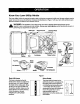
Know Your Lawn Utility Vehicle The Lawn Utility Vehicle is meant to be used as both a riding lawn mower and a utility cart. Its grass collector can be easily removed to expose the utility bed. Compare the illustrations in Figure 7 with your lawn utilityvehicle to learn about the location and features of its vadous controls. ,_ WARNING: operator's eyes, The causing operation severe of any eye riding damage.
ShiR Lever (off) position when (1) starting the engine, (2) travelling in reverse, and (3) if the operator leaves the seat. This lever is located on the left side of the fender and has three Choke clearly marked positions: FORWARD (F), REVERSE (R) and NEUTRAL (N). Follow the label on the unit to place the shift lever in the position desired. This is located in front of the seat frame. Pull the choke control outward to activate choke for starting engine; push it inward once the engine starts.
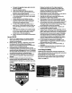
Brake Switch: This switch is located under the brake 1. 2. pedal assembly. The engine will not start without first depressing the brake pedal. This switch will also shut off the engine if the operator attempts to get off the unit without setting the parking brake, 3. Refer to the chart above for proper grade of oil. Use a high quality detergent oil classified =For service SF, SG,SH, SJ" or higher. Do not use special additives.
NOTE: Do not hold the key in the START position for longer than ten seconds at a time. Doing so may cause damage to your vehicle engine's electric starter. 7. • After the engine starts, press choke control inward, thus closing the choke. See Figure 8. NOTE: Do not leave the choke control • on while operating the unit. Doing so will result in a "rich" fuel mixture and cause the engine to run poorly. To move in reverse: Place blade control lever in OFF position.
4. Remove grass catcher to expose the utility bed. See Figure 9, Follow instructions on page 7 for grass catcher removal. Exemise caution in ddving the vehicle when hauling things on its utility bed. Replace the bag on to the mower. Hook the loose end of the bag retainer straps to the vehicle frame to secure the grass bag. Using as Mulcher NOTE: Total load capacity, including operator, should not exceed 400 Ibs. This vehicle is shipped with a mulch plug to recirculate grass clippings into the lawn.
General Recommendation • • • • Always observe safety rules when performing any maintenance. The warranty on this lawn utility vehicle does not cover items that have been subjected to operator abuse or negligence. To receive full value from the warranty, operator must maintain the equipment as instructed in this manual. We do not recommend the use of pressure washers or garden hose to clean your unit. These may cause damage to electrical components, spindles, pulleys, beadngs or the engine.
3. 4. Maintaining Remove the 5/8" hex flange nut which holds the blade to the blade spindle and the spindle shaft. Remove blade from the spindle. See Figure 11. Changing Engine Engine Oil 1. Disconnect spark plug wire and ground against engine. 2. Place the blade control lever in the disengaged (OFF) position and engage the parking brake. 3. Remove cutting deck by removing the three hairpin clips and flat washers that hold the deck to the hanger links. 4.
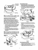
5. Engine Tune-Up Specifications Completely loosen the two screws that hold the cover of the air cleaner. Remove the entire air cleaner assembly from the base. Liftthe cover off the air cleaner. See Figure 13. • Armature air gap 0.006 - 0.014 inches • Spark plug gap 0.020 inches • Intake 0.004 - 0.006 inch • Exhaust 0.009 - 0.011 inch Cover Lubrication See Figure 15 for an illustration of the lube points described below. Base • • Figure 13 6.
2. Set the parking brake and push the vehicle. Ifthe rear wheels roll, adjust the brake following instructions on page 20. 1. 2. Remove throe screws holding the cup and battery holder to the frame of the unit. Remove red and black insulation caps from battery terminals. Tires _lb _r airARNING: pressure shown Never onexceed sidewall maximum of the tire. limit of !' // The recommended operating tire pressure is 20-22 psi for both sets of tires.
4. Wearing a pair of heavy work gloves to prevent injury, rotate the cutting blade so that it is pointed side to side and perpendicular to the dder. Measure the distance from each tip of the blade to the ground, If the distance from both blade tips to the ground is not the same, perform a side to side levelling of the deck. For levelling, remove the hairpin clip and flat washer shown in Figure 18. Thread the ferrule in or out as required. Check for correct adjustment.
4. Retighten jam nuts when proper tension is reached. Test the adjustment. Readjust if necessary. Jam Nut Jam Nut Deck Engagement Cable ............ Control Rod Adjust this ferrule / Figure 21 / / Wheel Alignment Figure 19 The front wheels should toe-in 1/16-5/16 inch. To adjust toe-in, follow these steps: Adjusting Speed Control Rod This adjustment is necessary when the vehicle cannot hold the full range of speeds, or shows belt drag (=creep")when the drive pedal is released. 1. 1.
Adjusting Brake A Shift Lever WARNING: Do not adjust the brake while engine is running. Be sure to block the wheels of the vehicle before attempting any adjustment on the brake cable. NOTE: Adjustments are done at the cable end; for adjustment of the calipers, see a Sears service center. IMPORTANT:The brake cable should be adjusted so that it has a bit of slack when the brake is released. The front cable bracket is mounted on the frame behind the pedal assembly.
disengaging completely. Fora properworkingmachine, usebeltsavailablefromSears. 1. 2. Follow Figure 25 for routing of belts and pulleys. Periodically check to see if these belts are too loose or damaged through wear and tear. If so, replace with new belt. NOTE: It is recommended Replace with new belt making sure that the hardware is propedy secured and the belts are on the inside of the belt keepers. Jack Spindle Replacement Check jack spindle whenever you replace upper deck drive belts.
2. 3. 4. , 5. 6. 7. 8. Remove the upper drive belt first by working from the back of the unit. Roll the belt off the idler pulley first and then off the transmission pulley. Next roll it off the variable speed pulley. Working from the side of the unit, pull the lower drive belt tension pulley to the right and roll the lower drive belt off this pulley. Using a 9/16 socket, remove the bolt holding the engine pulley, and drop the pulley down.
If the lawn utility vehicle is to be inoperative for a period longer than 30 days, follow the steps below for storage. 2. Preparing for Storage 3. Battery 1. Fully charge the battery with a 6 amp battery charger. NEVER store battery without a full charge. 4. NOTE: ff a charger with 6 amp output is not available, a lower output charger may be used for a longer period of time. Do not charge the battery at a rate higher than 6 amps as it can damage the battery and reduce its life. 2. 3. Equipment 1.
Trouble Engine failstostart PossibleCause RemedialAction Fuel tank empty, or stale fuel. Blocked fuel line. Faulty spark plug. 1. 2. 3. 4. 5. 6. 7. Disengage blade control lever Engage parking brake. Connect wire(s) to spark plug. Pull out the CHOKE control Fill tank with clean, fresh gasoline. Clean fuel line or replace fuel filter Clean, adjust gap or replace spark plug. 1. 2. 3. 4. 5. Unit running with CHOKE applied. Spark plug wire loose. Blocked fuel line or stale fuel. Vent in gas cap plugged.
Parts List for Craftsman For \ Lawn Utility Vehicle Model 247.270250 33 15 \ For reference only only 45 3\ For reference only* \ NOTE: For painted parts, please refer to the list of color codes below. Please add the applicable color code, wherever needed, to the part numbar to order a replacement part. For instance, if a part, numbered 700xxxx, is painted polo green, the part number to order would be 700-xxxx-0689.
Parts List for Craftsman Lawn Utility Vehicle Description Steedng Wheel Steering Wheel Cap Key No. 1. Part No. 731-1687 2. 3. 731-t459A 647-0055 4. 5. 683-0432 683-0433 6. 7. 683-0592 710-0191 8, 710-0599 9, 10. 710-0604A 710-0859 11, 710-1017 12. 13. 710-1681 710-3013 Hex Bolt 14. 15. 711-0242 711-0396 Spacer 16. 17. 711-1155 711-1531 18. 19. 712-0296 712-0380 20. 21. 712-0431 712-0692 22. 712-0714 23. 24. 712-3007 712-3017 25. 26. 714-0104 714-0145 27. 28.
Parts List for Craftsman Lawn Utility Vehicle Model 247.270250 16 For reference only / 11 IMPORTANT: For a proper working machine, use Factory Approved Parts. V-BELTS are specially designed to engage and disengage safely. A substitute (non OEM) V-Belt can be dangerous by not disengaging completely. NOTE: For painted parts, please refer to the listof color codes below. Please add the applicable color code, wherever needed, to the part number to order a replacement part.
Parts List for Craftsman Key No. Pert No, 618-04007 1. Lawn Utility Vehicle Model 247.270250 Key No. Part No. Transmission Assembly* 25. 736-0169 Description Lock Washer 3/8 Description 2. 619-0011 Spindle Housing 26. 736-0219 Bell Washer .39 x 1.13 x .062 3. 683-0446 Idler Bracket Assembly 27. 736-0247 Flat Washer 3/8 x 1.25" 4. 683-0447 Idler Bracket Assembly 28, 736-0427 Bell Washer .567 x 1.128 x .06 5, 710-0191 Hex Bolt 3/8-24 x 1,25" 29, 736-3052 Flat Washer .406 x 1.
Parts List for Craftsman Lawn Utility Vehicle Model 247.270250 48 5O I 2O I I I I NOTE: For painted parts, please refer to the list of color codes below. Please add the applicable color code, wherever needed, to the part number to order a replacement part. For instance, if a part, numbered 700-xxxx, is painted polo green, the part number to order would be 700xxxx-0689.
Parts List for Craftsman Lawn Utility Vehicle Model 247.270250 Key No. 1. Pert No. 757-04000 Description _eat 2. 683-0575 Support Bracket Assembly LH 3. 683-0576 Support Bracket Assembly RH Key No. Part No. 710-1752 38, 39. 711-1165 '12-0185 Description Special Screw Clevis Pin Speed Nut 1/4-20 * 4. 710-0604A TT Screw 5/16-18 x 0.625" 40. 42. 5. 710-1250 Carriage Boll 5/16 x 1.5" 43. 712-0692 Hex Lock Nut Flange Lock Nut 712-0640 Hex Nut 6. 710-1681 Hex Bolt M8-1.25: 20 44.
Parts List for Craftsman Lawn Utility Vehicle Model 247.270250 5 J / 11 47 46 For reference only 31 42 43 NOTE: For painted parts, please refer to the list of color codes below. Please add the applicable color code, wherever needed, to the part number to order a replacement part. For instance, if a part, numbered 700-xxxx, is painted polo green, the part number to order would be 700-xxxx-0689.
Parts List for Craftsman Key No. 1. 2, Lawn Utility Vehicle Model 247.270250 Part No. Description Key No. Part No. 683-0441 Shift Assembly: Front Lift 25. 783-1082 Description Deck _83..0442 Pivot Bracket Assembly 26. 710-0347 Hex Screw 3/8-16 x 1.75 _83-0448 Bracket Assembly: Lift Handle 27. 710-0514 Hex Bolt 3/8-16 x 1.0 4, 710-0641 Hex Bolt 1/4-20 x 2.25 28, 710-0650 "17"Screw 5/16-18 x 0,875 5. 710-1681 Hex Bolt M8-1,25: 20 30. 712-0417A Flange Nut 5/8-18 6.
Craftsman Lawn Utility Vehicle Model 247.270250 3 \ I I j6 Key No. 1. Part NO. 649-0126 Description Tube Assembly: Front Frame 2. 664-0107 Grass Catcher Bag 3. 710-1194 Mach. Screw #10-24 x 1.0 4. 712-0161 Lock Nut #10-24 5. 723-0383 Retainer Strap 6. 736-0400 Flat Washer 7. 749-1260 Side Tube: Frame 8. 749-1262 Bag Handle 9. 749-1269 Support Tube NOTE: For painted parts, please refer to the list of color codes below.
Parts List for Craftsman Lawn Utility Vehicle Model 247.270250 1 ® 2 / I0 Key No. Part No. 1. 611-0011 Description Shaft Assembly: Detent 2. 618-0072B Upper Housing Assembly 3. 610-0135 Drive Shaft Assembly: LH Brake 4. 61 0-04009 Axle Assembly 5. 661-0043 Brake Assembly: Yoke LH 6. 710-1325 TT Screw 1/4-20 x 1.625" 7. 8. 717-0678 Break Pad 719-0313B Lower Housing 9. 732-0863 Spring Detent 10. 737-0148 Grease 11. 741-0862 Ball: Detent: .250 12. 761-0202 Brake Disc 13.
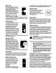
E ENGINE MODULE u 0 (1 729-0352 _ SEAT SWITCH _ Connector Connector ' - _ JL " _-_ a BRAKE Connector 729-0148 SWITCH _ I .J o 125 7L_..
Parts List for Craftsman Lawn Utility Vehicle Model 247.270250 Safety & Decorative Labels 777006242 ON STEERING (MODEL PLATE ON RIGHT CAP SIDE) 777122019 777S32028 777D06237 777S32029 777120887 777122016 777120889 | 777122020 777D06240 777120890 777D06241 777S30018 777D06238 @ Some of these symbols will be found on the engine or in the manual or labels on the lawn utility vehicle.
Parts List for Briggs & Stratton Engine 12607-0324 for Lawn Utility Vehicle Model 247.
Parts List for Briggs & Stratton Engine 12607-0324 for Lawn Utility Vehicle Model 247.
Parts List for Briggs & Stratton Engine 12607-0324 for Lawn Utility Vehicle Model 247.
Parts List for Briggs & Stratton Key No. 1 PaN No. Description 897639 Engine 12607-0324 2 399269 Cylinder Assembly Kit: Bushing Seal for Lawn Utility Vehicle Model 247.270250 Key No. IPart No.
Parts List for Briggs & Stratton Key No, 525 Part No. 495265 Engine 12607-0324 Description for Lawn Utility Vehicle Model 247.270250 Key No. Dipstick Tube Grommet Part No.
|ndice de materias Pdgina |ndice de materias Pdgina Mantenimiento ........................................ 54 Informacibn sobre la garantfa ................... 42 Prdcticas de funcionamiento seguras ...... 43 Determinacibn de la pendiente ................ 46 Monta}e ..................................................... 47 Funcionamiento ........................................ 49 Servicio y ajustes ................................... 58 Almacenamiento prolongado..................
ADVERTENCIA: La presencia de este simbolo indica que se trata de instrucciones importantes de seguridad que debe rospetar para evitar porter en desgo su seguridad personal y / o material y de otras personas. Lea y siga todas las instrucciones contenidas en este manual antes de intentar poner esta mdquina en funcionamiento. De no haeerlo puede ocasionar lesiones. Cuando encuentre este simbolo - respete la advertencia que aparece a continuaei6n del mismo.
5. 23. Compruebe los espaclo_ libres con cuidado antes de manejar bajo las ramas de los drboles, cableado, las aperturas de puertas, etc. cuando el operador pueda set golpeado o sacado de la unidad, Io que resultada en lesiones personales de gravedad. 24. Desenganche todos los embragues de los accesorios, presione completamente el pedal de freno y cambie a neutral antes de intentar arrancar el motor. 25. Su mdquinaestddiseSadaparacortarc_sped residencial normal de un alto no mayor a 10".
. Retirela Uavecuandodale la mdquina sinatencibn para preveflir el usonoautorlzado. Nunca permitaqua nifios menores de 14 a_os operen esta md,quina. Los nifiosde 14 afios y mdsdeben leer y comprender las instruccionesde operaci6n y las reglas de seguridadcontenidasen este manual y deben ser capacitados y supervisadosper unode los padres. 3. evitar qua se encienda de manera accidental.
VEA Y SOSTENGA UN POSTE ESTE N1VEL CON UN _RBOL VERTICAL DE ELECTRICIDAD LA ESQUINA DE UrN EDIFICIO 0 UNA VALLA -. DE lSo ID ADVERTENCIA: No pode en inclinacionescon pendientesmayoresa 15 grades(una elevacibnde aproximadamente 2-1/2 pies per cada 10 pies). Un vehfculoutilitariocortac_spedpuedevolcarsey causarlesionesgraves.SI operauna cortadoraque requiereempujarseen dicha pendiente,ser&extremadamentediffcUque mantengasu equilibrio y podrfaresbalar,provoc_ndoselesionesseveras.
Desempaque 1. 2. 3. 4. 5. 6. Tolva De Descarga Lateral la Unidad Retire todos los tornillos y grapas de la caja de madera. Sosteniendo los lados de la caja confirmeza, levante la tapa de la caja y colbquela a un lado. Evite pinchar los neumdticos. Retire y deseche la bolsa pl_,stica que cubre la unidad. Levante la parte posteriordel vehlculoy despeje el fondo de ta caja. Repita para el frente. Una ayudante puede ayudar.
Tolva del recolector NOTA: La bolsa para pasto debe estar colocada en su posici6n en el veh[culo utilitario cortac6sped, pare cualquier operaci6n de pods, incluyendo el forraje y la descarga lateral de recorte depasto. illo de mano 1. 2. de pasto Coloque la cubierta de la cortadoraen la posJci6r) mds baja deslizando la palanca de la cubierta haste la mnura apropiada.
CaracteHsticas generales del vehfculo utilitario cortacdsped El vehfculo utilitario cortacdsped estd dise_ado para set usado como una cortadora en la que puede montarse y un carro de servicio. Su recolector de pasto puede retirarse fdcilmente pare revelar la piataforma de servicios. Compare las ilustraciones en Figura 7 con su vehiculo utilitario cortacdsped para conocer rods acerca de la ubicacibn y caracterfsticas de los diversos controles del vehfculo.
Palanca de cambios en posicibndesenganchada (APAGADO) mientras (1)se arranca el motor, (2) estdviajando en reversa y (3) el operador deja su asiento. Esta palanca se Iocaliza al lado izquierdo de la defensa y tiene tres posiciones claramente sei_aladas:DE FRENTE (F), REVERSA (R) y NEUTRAL (N). Siga las instruccionesen la etiqueta en la unidad para colocar la palanca de cambios en la posici6n deseada. Control de tolva Se Iocaliza en la parte frontal del marco del asiento y debajo del asiento.
Interroptordecontrolde cuchillas:Esteinterruptor estdIocatizedo eniacotumna dedireccibn. Siei operador intentaarrencar elmotor,bajarse delasientoo retirarlabolsaparapastoconfapalanca decontrolde cuchiUas activa, se apagar6, el motor. 1. 2. 3, Interruptor de bolsa pare pasto: Este interruptorse Iocaiiza en ei cabezal detrds del motory forma parte del mecanismo de seguddad. Si el operedor intenta cortar el cdsped sin el recolectorde pasto colocado adecuadamente en el vehfcuio,se apagard el motor.
6. Gire la Ilave de encendidoen sentido de las agujas del reloj hasta la posicibn ARRANQUE. Despu_s de cluearranque el motor, suelte la Ilave. Regresard a la posicibnde MARCHA automdUcamente. ADVERTENCIA: No deje el asientodel vehfculo sin colocar primero la palanca de control de cuchillasen la posicidnde desenganche (APAGADO), presionando el pedal de freno y colocando el freno de mano. Si deja la unidadsin atencibn, apague el interruptory retire la Ilave.
Para vaciar el recolector I. 2. 3. 4. • de pasto Detenga por completo el cortac_sped,coloque el freno de mano y saque la ,ave del encendido. Salga del asiento. Desenganche 1ascorreas de la bolsa del marco de la cortadora. Tire la bolsa recolectora de pasta por las dos manijas y (16ve(ahasta el sitioapropiadode desecho. Mantenga una velocidad baja para permitirque los recortes de pasto tengan rodstiempo para ser molidos.
Recomendaciones • • •• • generales Siempre obedezca las reglas de seguridad cuando est_ realizando cualquier trabajo de mantenimiento. La garantfa en este vehfculo utilitariocortac_sped no cubre artfculosque hayan estado sujetosal abuso o negligenciadel operador. Para recibirel valor completo de su garantfa, el operador deberd mantener el equipo de acuerdo con Io indicadoen este manual. No recomendamos el uso de limpiadoresa presibn o mangueras de jardfn para limpiarsu unidad.
3. 4. Mantenimiento Retire la tuerca de bdda hexagonal de 5/8" que sostiene la cuchillaal vdstagoy al eje. Retire la cuchinadel vdstago, Vea Figura 11. Cambio I, 2. 3. _ubierta 4. Espaciador _ _'_V_tstag° D"--'-'-Tuerca de brida---,-_ _,_ F '°" _c°jlnete de Eje del vatstago Cuchilfa del motor de aceite del motor Desconecte el cable de la bujla y pbngalode manera que haga masa contra el motor.
5. Afloje los dos tomillosque sujetan la cubierta del filtro de alre. Retire el ensemble completo del filtro de aire desde la base. Levante la cubierta pare sacada del flltrode aire. Vea Figura t 3. Especificaciones Cubierta Pre4iltro Pare limpiar el cartucho, golpee ligeramente en el lado con papel plegado contra una superficieplana. Para limpiarel pre-filtro,sepdreiodel cartucho y Idvelo con detergente h'quidoy agua. Seque perfectamente con aim. Vuelva a ensamblar el pre-fi(troseco en el cartucho.
2. Coloque el freno de mano y empuje el vehleulo. Si los neumdticos traseros ruedan, ajuste los franos siguiendolas instruccionesen la pdgina 60. Acumulador el6ctrlco Neumdticos 4_b mdxima de intiadode los neumdticosque se ADVERTENCIA: Nunca exceda la presi6n muestra en la pared (ateral del neumdtico. La presibn de operacibn recomendada para los neumdticoses de 20-22 psi para ambos juegos de neumdticos.
4. Ajustes ADVERTENClA: Nunca intente hacer ajustes mientras la mdquina estd en funcionamiento, excepto que est_ especificamente recomendado en el manual del operador. 5. ADVERTENCIA: Para otrosajustes, desconecte el cable(s) de la bujia de encendidoy condctelosa tierra con el motor. Luego proceda a realizar los ajustes. Posicibn 6. 7. del asiento 8. Utilice un par de guantes para trabajo pesado para prevenirlesiones, gire la cuchillapara que apunte lado a 1adoy perpendiculara la transmisibn.
4. Vuelva a apretar las contratuercas cuando tenga la tensi6n apropiada. Pruebe el ajuste. Vuelva a ajustar en caso necesado. Contratuerca Enganche de la cubier Cable / / ! / Figura 21 Alineacibn de las ruedas Figura 19 Laa ruedas delanteras deben tener una convergencia de 1/16 -5/16 pulgadas. Para ajustar la convergencia, siga estos pasos: 1. Usando una ,ave de 9/16", retirela tuerca hexagonal y la arandela de cierre que sostiene lajunta esf6dca al segmento de direcci6n. Vea Figura22.
Freno ADVERTENCIA: No ajuste el freno mientrasel motorestd en marcha. AsegL_resede bloquear las ruedas para que el vehiculo no pueda moverse antes de realizarcualquier ajuste en el cable de frenos. 7, y suj_tela con la arandela y la horquiliaque quitb antedormente. Mueva la barrade cambio a (N) y controleque el ajuste sea correcto. Palanca de cambios NOTA: Los ajustes se hacen per el extremo del cable. Para ajustar los calibradores, acuda a un centro de servicioautorizado.
uso de herramientas especiales. Lea todo el siguiente procedimiento y determine si puede realizarlo completamente antes de intentarlo, en caso contrario contacteat centro de servicio Sears. IMPORTANTE: Las correae V que se encuentran en su veh|culo utllitariocortacdspedestdn especialmente dise_adas pare engancharse y desengancharse con seguridad. Una correa V sustituta(no- OEM) puede resultar peligrosasi no se desengancha compietamente.
9. Trabajando pordebajodelvehiculo, vuelvaainstalar lapoleadelvdstago deconexibn conelpemoque retirbantedormente, 10. Levante laplataforma deservicios deregreso ensu posicibn deoperacibn, vuelvaa unitelrecolector de pastos siserequiere yvuelvaa conectarel cable de la la polea de velocidad variable y la polea de transmisi6n. Reemplaca las correas superiores de la cubierta siguiendo las instrucciones anteriores. Reemplace la correa de propulsibn.
Salvando el equipo b. Si el tanque contiene t_nicamente gasolina, haga funcionar el motor hasta que se agote el combustible. c. Si agrega un aditivo a la gasolina en el tanque, t_agafuncionar el motor durante vados minutos despues de agregarlo para que el aditivo circule por el carburador. Refidrase a la pdgina 51 para obtener detalles sobre aditivos. Mientras el motortodavla estdtibio, cambie el aceite. Consulte las instruccionesen la pdgina 55. Retire la bujfa y vacfe aproximadamente 0,5 oz o 15 ml.
Get it fixed, at your home or ours! For repair of major brand appliances in your own home... no matter who made it, no matter who sold it! 1-800-4-MY-HOME ® Any"me, dayornight (1-800-469-4663) (U.S.A. and Canada) www.sears.com www.sears.ca For repair of carry-in products likevacuums,lawnequipment, and electronics, call for the location of your nearest Sears Parts and Repair Center. 1-800-488-1222 Any,me, day or night (U.S.A. only) www.sears.