Owner's Manual JCRAFTSMAN°J 25.0 HP ELECTRIC START 48" MOWER AUTOMATIC GARDEN TRACTOR Model No. 917.275222 • Safety • Assembly • Operation • Maintenance • Repair Parts CAUTION: Read and follow all Safety Rules and Instructions before operating this equipment. For answers to your questions about this product, Call: 1-800-659-5917 Sears Craftsman Help Line 5 am - 5 pro, Mon - Sat Sears, Roebuck and Co., Hoffman Estates, II 60179 Visit our Craftsman website:www.sears.
Warranty ............................................... 2 Safety Rules ......................................... 3 Product Specifications .......................... 6 Assembly .............................................. 9 Operation ............................................ 14 Maintenance Schedule ...................... 21 Maintenance ....................................... 21 Service and Adjustments.................... 25 Storage ............................................... 33 Troubleshooting ..
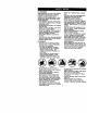
IMPORTANT: This cuffing machine is capable of amputating hands and feet and throwing objects. Failure to observe the following safety instructions could result in sadous injury or death. I. GENERAL OPERATION U, SLOPE OPERATION • Reed, understand, and follow all Slopes are a major factor related to loss-ofinstructionsin the manual and on the control and tipover accidents, which can remachine before starting. suit in severe injury or death.
IlL CHILDREN Tragic accidents can occur if the operator is not alert to the presence of children. Children are often attracted to the machine and the mowing activity. Never assume that children will remain where you last saw them. • Keep children out of the mowing area and under the watchful care of another responsible adult. • Be alert and turn machine off if children enter the area. • Before and when backing, look behind and down for small children. • Never carry children.
• Use slow speed. Choose a low gear so that you will not have to stop or shift while on the slope. • Avoid startingor stopping on a slope. If tires lose traction, disengage the blades and proceed slowly straight down the slope. • If machine stops while going uphill, disengage blades, shift into reverse and back down slowly. • Do not turn on slopes unless necessery, and then, turn slowly and gradually downhill, if possible. _Look for this symbol to point out important safety precautions.
PRODUCT SPECIFICATIONS GASOLINE 3.5GALLONS CAPACITY AND TYPE: OIL TYPE API-SF-SJ): OIL CAPACITY: UNLEADED REGULAR SAE 10W30 (ABOVE 32°F) SAE 5W-30 (BELOW 32°F) W/FILTER: 4.5PINTS SPARK PLUG: IGAP: .030") GROUND W/O FILTER:4.0PINTS CHAMPION RC12YC FORWARD: 5.8 SPEED(MPH): TIRE PRESSURE: REVERSE: 2.1 FRONT: 14 PSI REAR: 10 PSI CHARGING SYSTEM: 15AMPS@ 3600RPM BATTERY: AMP/HR: 35 MIN. CC/_ 280 CASE SIZE:UIR 45-55 FT.
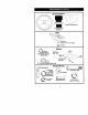
Steering Wheel Steering Sleeve SteedngWheellnse_ Steedng Sleeve Extension Seat (1) Washer 17/32 x 1-3/16 x 12 Gauge _(1) Knob Mower _2)Flanged (5) Retainer Spdngs (double loop) P'ms Assembly (1)Front Plate (2) Retainer Spdngs (single loop) f (4) Adjusting Bar @ @ Gauge Wheels (4) Shoulder Bolt /!'_L_ _(4) Spdngs Retainer @ L_ 4) Wheels 4) Lockout 3/8-16 I (_ (4) Clevis Pins (4) Washers 3/8 x 3/4 x 14 Ga,
Video Cassette Keys (1) Oil Drain Tube 8 Slope Sheet
Yournew tractor has been assembled at the factory with exception of those parts left unassembled for shipping purposes. To ensure safe and proper operation of your tractor all parts and hardware you assemble must be tightened securely. Use the correct tools as necessary to insure proper tightness. TOOLS REQUIRED FOR ASSEMBLY A socket wrench set will make assembly easier. Standard wrench sizes you need are listed below.
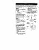
HOWTO SET UPYOURTRACTOR CHECK BATTERY 1. Lift hood to raised position. NOTE: If thisbattery is put into service after month and year indicated on label (label located between terminals) charge battery for minimum of one hour at 6-10 amps. (See "BATTERY" in Maintenance section of this manual for charging instructions). -=t_i_o-.y-O,, Y "" 5. Pivot seat and pan forward and assemble adjustment knob and fl; washer loosely. Do not tighten. 6. Lower seat into operating positioi sit in seat. 7.
TO ROLLTRACTOR OFF SKID (See Operation section for location and function of controls) 1. Press llft lever plunger and raise attachment llft lever to its highest posiUon. 2. Release perking brake by depressing brake pedal, 3. Place freewheel control in freewheeling position to disengage transmission (See "TO TRANSPORT" in the OperaUon secUon of this manual). 4. Roll tractorforward off skid.
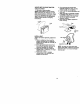
7. Place the suspension arms on outward pointing deck pins. Retain with double loop retainer spdng with loops up as shown. 8. Install front plate assembly to tractor suspension brackets and retain with single loop retainer spdngs as shown. 9. Position front plate assembly between front mower brackets. Raise deck and plate assembly to align holes and insert flanged pins. Secure pins with double loop retainer spdngs between the plate assembly and mower brackets.
V'CHECKUST Before you operateand enjoy your new tractor,we wish to assure that you receive the best performance and satisfaction from this Quality Product. Please review the following checklist: ,/'All assembly instructions have been completed. `/No remaining loose parts in carton. `/Battery is propedy prepared and charged. (Minimum 1 hour at 6 amps). `/Seat is adjusted comfortably and tightened securely. .,/All tires are prepedy inflated. (For shipping purposes, the tires were ovednflated at the factory).
These symbols may appear on your tractor or in literaturesupplied with the product. Learn and understand their meaning.
KNOWYOURTRACTOR READ THIS OWNER'S MANUAL AND SAFETY RULES BEFORE OPERATING YOUR TRACTOR Compare the illustrationswith your tractor to familiadze yourself with the locations of vadous controls and adjustments. Save this manual for future reference.
The operation of any tractor can result in foreign objects thrown into the eyes, which can result in severe eye damage. Always wear safety glasses or eye shields while operating your tractor or performingany adjustments or repairs. We recommend a wide vision safety mask over spectacles or standard safety glasses. HOWTO USEYOURTRACTOR TO SET PARKING BRAKE Your tractor is equipped with an operator presence sensing switch.
The cutting height range is approximately 1-1/2" to 4-1/2". The heights are measured from the ground to the blade tip with the engine not running. These heights are approximate and may vary depending upon soil conditions, height of grass and types of grass being mowed. • The average lawn should be cut to approximately 2-1/2 inches during the cool season and to over 3 inches dudng hot months. For healthier and better looking lawns, mow often and after moderate growth.
TO TRANSPORT When pushing or towing your tractor, be sure to disengage transmission by placing freewheel control in freewheeling position. Free wheel control is located at the rear drewhar of tractor. 1. Raise attachment lifl to highest position with attachment lift control. 2. Pull freewheel control out and into the slot and release so it is held in the disengaged position. • Do not push or tow tractor at more than two (2) MPH. • To reengage transmission, reverse above procedure.
NOTE: Beforestartilg, readthe warm and coldstaring proceduresbolow. 6. Insert key into ignition and turn key clockwise to "START" position and release key as soon as engine starts. Do not run starter continuously for more than fifteen seconds per minute. If the engine does not start after several attempts, push choke control in, wait a few minutes and try again. If engine still does not start, pull the choke control out and retry. WARM WEATHER STARTING (50° F and above) 7.
5. Move motion control lever to neutral (N) position. Shut- off engine and set parking brake. 6. Engage transmission by placing freewheel control in driving position (See =TO TRANSPORT" in this section of manual). 7. Sitting in the tractor seat, start engine. After the engine is running, move throttle control to half (1/2) speed. Disengage parking brake. 8. Slowly move motion control lever forward, after the tractor moves approximately five (5) feet, slowly move motion control lever to reverse position.
FILL IN DATES REGULAR SERVICE f CheCkBrakeOper&tlon T I_ ;11_ ChOCkTire pre_ure k/ i Ch_k Operator PreSence and Inted_k Systems _# R Ch._ forLoo...F.t..
TRACTOR Always observe safety rules when performing any maintenance. BRAKE OPERATION if tractor requires more than six (6) feet stopping distance at high speed in highest gear, then brake must be adjusted. (See "TO ADJUST BRAKE" in the Service and Adjustments section of this manual). TIRES • Maintain proper air pressure in all tires (See "PRODUCT SPECIFICATIONS" section of this manual). • Keep tires free of gasoline, oil, or insect control chemicals which can harm rubber.
• Keepbattery andterminals clean. • Keep battery boltstight. • Keep small vent boles open. • Recharge at 6-10 amperes for 1 hour. NOTE: The odginal equipment battery on your tractor is maintenance free, Do not attempt to open or remove caps or covers. Adding or checking level of electrolyte is not necessary. TO CLEAN BATTERY AND TERMINALS Corrosion and dirt on the battery and terminals can cause the battery to _leak" power. 1. Remove terminal guard. 2.
OilDrainValve Draiia__cIosed 9, Reassemble air cleaner, cartridge plate, and nut. 10, Reinstall air cleaner cover and secure by tightening knob. and Foam Pre-Cleaner Cartridge Plate CLEAN AIR SCREEN LockedPosition Rubber Air screen must be kept free of dirt and Seal chaff to prevent engine damage from overheating. Clean with a wire brush or compressed air to remove dirt and Nut stubborn dried gum fibers.
CAUTION: BEFORE PERFORMING ANYSERVICE ORADJUSTMENTS: kl. Depress brakepedal fullyandsetparking brake. 2.Place attachment clutchin =DISENGAGED" position, 3, Tum ignition key =OFF" and remove key. 4. Make sure the blades and all moving parts have completely stopped. 5. Disconnect spark plug wire from spark plug and place wire where it cannot come in contact with plug. TO INSTALL MOWER TRACTOR Fellow procedure described in =INSTALL TO REMOVE MOWER MOWER AND DRIVE BELT"in the 1.
BOTH FRONT LINKS MUST BE EQUAL IN LENGTH NOTE: Each full turn of adjustment nut will change mower height about 3/16". • Recheck measurements after adjusting. BottomEdgeof Mowerto Ground Bottom Edgeof Mowerto Ground \ / .Nut =G" Nut FRONT-TO-BACK ADJUSTMENT IMPORTANT: Deck must be level side-toside. If the following front-to-back adjustment is necessary, be sure to adjust both front linksequally so mower will stay level side-to-side.
R.H. Mandrel Cover BeltTensionRod (Disengaged Electric , Crutch Pultey P_ition) _,_7 # Idler Pulleys Spring Arm R.H. Mandrel R.H. Suspension Arm Primary Idler Arm TO REPLACE MOWER BLADE DRIVE BELT Park the tractoron level surface. Engage parking brake. 1. Remove mower ddve belt (See "TO REPLACE MOWER DRIVE BELT" in this section of this manual). 2. Remove mower (Sou =TO REMOVE MOWER" in this section of this manual). 3. Remove screws from L.H. mandrel cover and remove cover. 4.
TO ADJUST ATTACHMENT CLUTCH The electric dutch should provide years of service. The clutch has a built-inbrake that stops the pulley within 5 seconds. Eventually,the internal brake will wear which may cause the mower blades to not engage, or, to not stop as required. Adjustments should be made by your nearest authodzed service center/ department. 1. Make sure attachment dutch and ignitionswitches are in "OFF" position. 2. Adjust the three nylon Iocknuts until space between clutch plate and rotor measures .
TO ADJUST STEERING WHEEL ALIGNMENT If staering wheel crossbars are not horizontal (left to right)when wheels are positioned straight forward, remove steering wheel and reassemble per instructionsin the Assembly section of this manual, FRONT WHEEL TOE-IN ADJUSTMENT Front wheel tee-in is required for proper steering operation. Toe-in was set at the factory and adjustment should not be necessary.
INTERLOCKS AND RELAYS Loose or damaged widng may cause ) tractorto run poorly,stop running, or prevent it from starting. • Check widng. See electrical widng diagram in the Repair Parts section TO REPLACE FUSE Replace with 30 amp automotive-type plug-in fuse. The fuse holderis locate( behind the dash. REPLACING BATI'ERY _CAUTION: Do not short battery terminals by alloWinga wrench or any other object to contact both terminals at the same time.
ENGINE Maintenance, repair, or replacement of the emission control devices and systems, which are being done at the customers expense, may be performed by any non-read engine repair establishment or individual. Warranty repairs must be performed by an authodzed engine manufacturer's service outlet. TO ADJUST THROTTLE CONTROL CABLE The throttle control has been preset at the factory and adjustment should not be necessary. Check adjustment as descdbed below before loosening cable.
NOTE: The high idle is set at the factory and cannot be adjusted. 2. Idle speed setdna - With throttle control lever in slow position, engine should idle at 1200 RPM. If engine idles too slow or fast, turn idle speed adjusting screw in or out until correct idle is attained. 3.
Immediately prepare your tractor for storage at the end of the season or if the tractor will not be used for 30 days or more, CAUTION: Never store the tractor with gasoline in the tank inside a building where fumes may reach an open flame or spark. Allow the engine to cool before stodng in any enclosure. TRACTOR Remove mower from tractor for winter storage. When mower is to be stored for a period of time, clean it thoroughly, remove all dirt, grease, leaves, etc. Store in a clean, dry area. 1.
TROUBLESHOOTING CHART PROBLEM Willnot start CAUSE 1. Out of fuel. 2. Engine not "CHOKED" properly. 3, Engine flooded. CORRECTION 1. Fill fuel tank. 2, See "TO START ENGINE" in Operation section, 3, Wait several minutes before attempting to start. 4. Bad spark plug. 4. Replace spark plug. 5. Dirtyair flter, 5. Clean/replace air filter. 6, Dirtyfuel filter, B, Replace fuel filter. 7, Water in fuel, 7. Drain fuel tank and carburetor, refill tank with fresh gasoline and replace fuel filter. 8.
"rROUBLESHOO_NG CHART PROBLEM CAUS E CORRECTION Lossofpower 1. Cuffing too much grass/too fast. 2. Throttle in =CHOKE" position. 3. Build-up of grass, leaves and trash under mower. 4. Dirty air filter. 5. Low oil level/dirty oil. 6. Faulty spark plug. 1. Set in =Higher Cut" position/ reduce speed. 2. Adjust throttle control. 7. Dirty fuel filter. 8. Stale or dirtyfuel. 9. Water in fuel 10.Spark plug wire loose. 11. Dirty engine air screenffms. 12. Dirty/clogged muffler. 13.Loose or damaged widng. 14.
TROUBLESHOOTING CHART CAUSE PROBLEM Vlower blades will _ot rotate Poor grass discharge Headlight(s) not ,working fso equipped) CORRECTION 1. Obstruction in clutch mechanism. 2. Worn/damaged mower ddve belt. 3. Frozen idler pulley. 4. Frozen blade mandrel. Engine "backfires' when turning engine "OFF" 3. Replace idler pulley. 4. Replace blade mandrel. 1. Place throttle control in "FAST" position. 2. Travel speed too fast. 2. Shift to slower speed. 3. Wet grass. 3. Allow grass to dry before mowing. 4.
SCHEMATIC TRACTOR - MODEL NUMBER 917.275222 BATTERy ..... t C SOLENC_D i .... i ..... J i GI (PEDALUP) J L. PTO D ...... :_ i t ---m, =.
ELECTRICAL TRACTOR - MODEL NUMBER 917.275222 / 26 i ......................... r ....
TRACTOR- MODEL NUMBER 917.275222 ELECTRICAL KEY NO. 1 2 8 10 11 12 16 21 22 25 26 27 28 29 30 33 40 42 45 46 50 79 81 89 PART NO, 144927 74760412 7603J 145211 150109 145769 153664 166184 4152J 150755 108824X 73510400 170697 160784 175566 140403 170238 154336 122822X 169635 174652 163996 10_48X 169639 DESCRIPTION Battery Bolt Hex Head 1/4-20 x 3/4 Tray, Battery Bolt 1/4-20 x 7.
TRACTOR - MODEL NUMBER 917.275222 CHASSIS ANDENCLOSURES 138 5 140 37 68 31 17_.._ .
TRACTOR-MODEL NUMBER917.275222 CHASSIS ANDENCLOSURES KEY NO. PART NO.
TRACTOR-MODEL NUMBER 917.
TRACTOR- MODEL NUMBER 917.275222 GROUND DRIVE KEY NO. PART NO.
TRACTOR-MODEL NUMBER 917.
TRACTOR - MODEL NUMBER 917.275222 STEERING KEY NO. PART NO.
ENGINE TRACTOR-MODEL NUMBER 917.275222 25 2t _ t8 1S 20 17 37 29 \ B 16 39 I SPARK KEY PART NO. NO. 1 2 8 9 10 11 12 15 16 17 18 20 21 22 24 25 26 27 28 29 Engine (See Breakdown) Kohler Model No. CV26-69940 149723 Mu61er 121361X Pulley V-Idler 177748 Keeper Asm. Belt Engine 175288 Bushing 174605 Clutch Electric 143996 Pulley Engine VGT Elect Clutch 151346 Tank Fuel Rear 3.
TRACTOR - MODEL NUMBER 917.275222 SEAT ASSEMBLY KEY NO, PART NO. DESCRIPTION 1 2 3 4 5 6 7 8 10 12 13 140124 140551 140675 127018X 145006 STD541437 124181X 171877 174894 121246X 121248X Seat Bracket, Pivot Seat Strap, Fender BOlt, Shoulder 5/16-18 x 62 Clip, Push In, Hinged Nut, Crownlock 3/_-16 Unc Spring, Seat Cprsn BoB 5116-18Uncx3/4 w/Sems Pan, Seat Bracket, Mounting Switch Bushing, Sr_p KEY NO. PART NO.
DECALS TRACTOR - MODEL NUMBER 917.275222 17 6 18 17 3 15 15 22 23 11 KEY NO. pART NO. 1 2 164096 149516 3 4 5 6 7 8 9 10 11 12 171702 171703 140837 133644 177664 164884 163204 156439 177781 177554 DESCRIPTION DecalDash Decal BaSery DNGI_JPSN ENGAsm DeCal Hond RH Graftsman DeCal Hood LH Craftsman Decal Brake Parking Saddle Decal Maintenance DeCal Engine Decal Blower Hsng Kohl Decal.
TRACTORMODEL NUMBER 917.275222 LIFTASSEMBLY 40 35 73 43 38 39 0 r,... 10 I 29 tt 23 24 78 75 7_ KEY NO. PART NO. DESCRIPTION 1 2 3 4 5 6 7 8 9 10 11 15 16 18 19 20 21 23 24 26 29 30 121006X 177535 159189 12000022 19292016 71110624 175830 175831 122364X 2876H 175375 6TD541437 674A247 143363 STD551(_7 5328J STD523710 STD624008 73350800 73680800 150233 110807X Rod Asm., Lever Shaft Asm., Lift Vgt Lever Asm., Lift Rh E-Ring Truarc#51334B7 Washer 29132 x 1-114 x 16 Ga.
MOWER DECK TRACTORMODEL NUMBER 917.
MOWER DECK KEY NO. PART NO. 1 3 5 6 174346 138017 4939M 130832 8 11 13 14 15 16 17 15 19 20 21 24 25 26 27 26 29 30 31 32 33 36 37 39 42 43 45 46 47 TRACTORMODEL NUMBER917.275222 DESCRIPTION DeckWetdrnent Mower 48 Bracket Asm., Sway Bar Retainer Spring Arm, Suspension, Rear (Sway Bar) 174365 Bolt 7/16 Asm. Blade 173920 Blade 137553 Shalt Asm. wFLower Bear ing 174356 MandrelAsr_ 110485X Bearing, Ban, Mandrel 174493 Stripper Mandrel Deck 72110610 Bolt RDHD Sq Neck 3/6-16xl.
TRACTOR - MODEL NUMBER 917.
TRACTORMODEL NUMBER 917.275222 TRANSAXLE-MODEL NUMBER 311-3500 KEY NO. PART NO.
TRACTOR-MODEL NUMBER 917.
TRACTORMODEL NUMBER 917,275222 KOHLER ENGINE-MODEL NUMBER CV26, TYPE NUMBER 69540 HEADNALVF.JBREAT KEY NO. PART NO, 1 24-033-03-S 2. 3. 4. 24.041-23-S 24.096-5g-s M-645020-S 5. 6. 7. X-75-23-S 25-351-01-S 24-755-66-S 8. 9. 10. 11. 12. 13. 24-411-05-S 24-041-37-S 24-318-72-S 25o186-01-S 24-599-01-S M-640034-S 14 15. 16. 17. 24-072-09-S 24-468-16-S 24-100-10-S 24.755-74-S 18. 19. 2g. 21. 23. 24. 25. 26. 27. 25. 29. 24-153-16-S 24-086-32-S 24-445-g1-s 24-016-01-S 24-016-02-S 24-017-01-S 24-017.
TRACTOR-MODEL NUMBER 917.
TRACTOR- MODEL NUMBER 917.275222 KOHLER ENGINE-MODELNUMBERCV26, TYPE NUMBER69540 IGRITION/CHARGING KEY NO. pART NO. 1. 54-755-15-S 2. M-403025-S 3. 4. 5. 6. 7. X-25-92-S 24-112-04-S 25-086-47-S 24-157-03-S 12-086-14-B 8, 9, 10. 11, 12, 13, 12-468-03-S X-42-15°S 24-025-14-S 25-403-03-S X-25-92-S 24-086-18-S 14. 15. 16. 236602°S 12-132°06-S 54-755-09-S 17. 18. 24-126-71-S M-548025-S 19. 20. 21. 22, 23, 47 154 01-S 48-154-02-S X-25-63-S 24-584-15-S M-561025-S 24, M-448010.S 25.
TRACTOR - MODEL NUMBER 917.275222 KOHLER ENGINE-MODEL NUMBER CV26, TYPE NUMBER 69540 .;TARTING SYSTEM I ENGINE CONTROLS ! s 9 1S--_ t3..._'v.
TRACTOR - MODEL NUMBER 917.275222 KOHLER ENGINE-MODELNUMBER CV26, TYPE NUMBER 69540 STARTING KEY NO. PART NO. 1. 2. M-641080-S M-636080-S 3. 12-098-63-S 4. 5. 6. 7. 8. 9. 10. 11. 12. 13. 14. 15. 12-061-62-S 52-100-10-S 12-090-10-S 24-755 84-S 12-239-61-S 52-435-02-S 52.106-09-S 12.170-03-S 12-471-01-S 52-221-01-S 52 323 03-S 52 089 Gg-s 16. 17. 18. 52-168 01-S 52 2_1 05-S 12-301-01-S ENGtNE OIL PAN/LUBRICA'nON SYSTEM KEY NO. PART NO. Nut, hex. flange M8x1.25 Screw, hax. flange I_SX'_.
TRACTOR-MODEL NUMBER 917.
TRACTOR-MODEL NUMBER 917.275222 KOHLER ENGINE-MODEL NUMBER CV26, TYPE NUMBER69540 FUEL CRANKSHAFT SYSTEM KEY PART NO. NO. KEY NO. PART NO. DESCRIPTION 1. 2. 24`014-72-S 52-139-09-S Crankshaft Plug, oup (Includes 1. 24`053-81-S 2. 3. 24-041-15-S 24-053-27 4. 5. 6. 8. g. 10. 24 041 14-S M-62g095-S M-64106g-s 25-353-03-S X-426-g-s 24`086-12-S 2) EXHAUST KEY NO. PART NO. DESCRIPTION 1. 2. 24`041`02-S 25`072`04-S 54-522_20 24-782-23 24-755-108-S Gasket, exhaUst (2) Stud, M8x1.
SUGGESTED GUIDE SIGHTING GUIDE _/_ _U_ FOR SIGHTING SLOPES FOR SAFE OPERATION ONLY RIDE UP AND DOWN HILL, NOT ACROSS HILL erate your Tractor up and down the face of slopes (not greater than 15°), never across the face. Make turns gradually to prevent tipping or loss of control. Exercise extreme caution when changing direction on slopes.
For repairofmajorbrandappl_ncesin your own home... no matterwho made it,no matterwho soldit] 1-800..4-MY-HOM E_ Anytme, dayornight (1-800-4Sg-,_63) (U.,S._ andCanada) Forrepair of cany-inproductslike vacuums,lawnequipment,and electronics, callforthe nearestSears Partsand RepairCenter. Forthe replacementparts,accessories and owner'smanuals thatyouneed todo-it-yourself, callSears PartsDIrect-_! 1-800-366-PART (1-eoo_6_7278) 6 a.m.- 11 p.m., 7days aweek (u.,s.A.