
Owners manual

20
SERVICE AND MAINTENANCE
Tines
The tines will wear with use and should be inspected at the beginning of each tilling
season and after every 30 operating hours. The tines can be replaced. Refer to the
Parts List section of this manual for part numbers.
Tine Inspection
With use, the tines will become shorter, narrower and pointed. Badly worn tines will
result in a loss of tilling depth, and reduced effectiveness when chopping up and
turning under organic matter.
Removing/Installing a Tine Assembly
1. Remove the tine shield end covers and side shields by removing the three
wing nuts on each side that secure them.
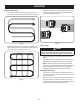
2. A tine assembly consists of a left hand tine and a right hand tine.
NOTE: The tine assembly moves in a counter-rotating motion with the sharp
edges of the tines positioned to enter the soil first when counter-rotating.
Note this position of the tines for reinstallation of the new tine assemblies.
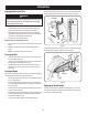
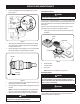
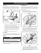
3. To remove a tine assembly, simply remove the internal cotter pin securing
the clevis pin. See Figure 29.
Clevis Pin
Internal Cotter
Pin
Figure 29
4. Remove the clevis pin and slide the assembly to the outside of the unit and
off of the tine shaft.
5. Before reinstalling the tine assembly, inspect the tine shaft for rust, rough
spots or burrs. Lightly file or sand, as needed. Apply a thin coat of grease to
the shaft.
6. Install each tine assembly so that the cutting (sharp) edge of the tines will enter
the soil first when the tiller moves forward. Keep in mind that these tines are
counter-rotating, so secure the tine assembly to the tine shaft using the clevis
pin and internal cotter pin.
Adjustments
Handle
The handle may be adjusted to the desired height. Refer to the Assembly section for
details.
Secondary Clutch Cable Adjustment
If additional adjustment is necessary after the primary adjustment from the
Assembly section can no longer be used, the secondary adjustment can be
performed as follows:
1. Remove the belt cover as instructed the Belt Replacement on page 21.
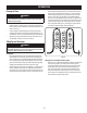
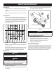
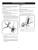
2. Locate the spring at the end of the cable. See Figure 30.
Upper Nut
Lower Nut
Idler Pulley Bracket
Figure 30
3. Loosen the upper nut, then tighten or loosen the lower nut until the proper
tension is reached.
4. Once the proper tension is reached, re-tighten the upper nut to secure the cable.