
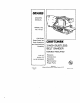
Instruction manual


MAINTENANCE
ir"lv_l-'l: I_11_[e_l,&M_I=1_It_l;I; LTItO]I_tqqlIkl =lh] _lll¢iel: fzl =IILILv,F_I_UIe]=l_|I [W_,IR _1=1".II,_TN=lLvli=_i m'J=,l:| i_le pp_=1_Ol1
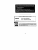
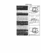
TIMING BELT REPLACEMENT SMALL PULLEY
D(SCONNECT SANDER FROM POWER SUPPLY
BEFORE SERVICING
WHEN REPLACING TIMING BELT, USE REPLACE.
MENT BELT NUMBER 989368-000 ONLY. See Key
Number 5 on Parts List, Page 11
1 Remove sanding belt from sander. See installing
and adiusting sanding belt, Page 5. NOTE:
REMOVING THE SANDING BELT WILL
SIMPLIFY THE PROCESS OF INSTALLING
YOUR NEW TIMING BELT,
2 Remove the two belt cover screws Then remove
the belt cover See Key Numbers 1 and 2 on ex-
ploded view and parts list, pages 10 and 11
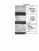
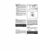
3 Force old belt from small pulley with a
screwdriver and removeJt fromlarge pulley If it
is worn out, simp{y cut the old belt and remove it.
4. Install new belt over large pulley first. See
Figure 10
5 Holding ihe belt as shown in Figure 11, press the
belt onto the smal_ pulley NOTE: TO SIMPLIFY
THE PROCESS, TURN THE LARGE PULLEY AS
YOU PRESS THE BELT ONTO THE SMALL
PULLEY.
6 Reass3mble belt cover an0 screws
_r_r_'_NEVER ATTEMPT TO OPERATE
YOUR SANDER WITHOUT BELT COVER IN
PLACE
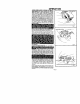
SWITCH REPLACEMENT
DISCONNECT THE SANDER FROM POWER SUPP-
LY WHILE REPLACING PARTS OR MAKING AD-
JUSTMENTS.
1 Remove the handle cover and screws. NOTE THE
LOCATIONS OF ALL WIRING IN THE HANDLE
AND HOW EACH CONNECTION IS MADE TO
THE SWITCH. Connections and wiring position
must be identical when installing the new
switch See Figure 12
2 Lift the switch away from the handle, then release the
leads to the switch by inserting a 1/32 in. diameter pin or
nail into each switch lead receptacle. See Figure 13.
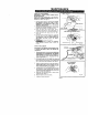
3 Make the lead connections to the new switch by
pushing each lead as far as possible into the
switch lead receptacles. Pull on leads to check
lead connections with lead receptacles.
4, Arrange the wiring in the handle so that it will not
be pinched or contact screws when the handle
cover and screws are replaced, then position the
switch in place. See Figure 12
5 Place the cord and bend relief in their correct
locations, See Figure 12.
6 Replace handle cover and screws,
7. Tighten all screws securely.
Page 8
LARGE PULLEY
IELT_VER BELT
COVER SCREWS Fig 10
APPLY PRESSURE
HERE AND TURN LARGE PULLEY
1/32 IN. DIAMETER
NAiL OR PIN
Fig. t3