
Owner`s manual


TYPICAL OPERATIONS
HELPFUL HINTS - MAKING CUTTER SIZE
SELECTIONS
AS you can see listed in the accessories, a wide
variety of cutters is available. Therefore, there is a
variety of sizes, grooves, curves and angles involved.
This often creates the need to estimate the
AVERAGE CUTTING DIAMETER when making cutter
size selections on the front panel. The following ex-
amples Illustrate how to estimate, the average cut-
ting diameter. REMEMBER: We recommend that
cuts be made at a depth not exceeding 1/8" and that
several passes be made to reach depths of cut
greater than 1/8"
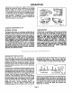
See Figure 13. In this illustration a V-groove cutter is
being used to make a 5/16" deep cut. To find the
average cutting diameter, add the maximum
diameter (5/8") to the minimum diameter (0), then
multiply by 1/2. The average diameter of the cut
equals 5/16". Since 5116" lies between the "1/4
inch" and "3/8 inch" position on the front panel,
either could be used. Difficulty in controlling, dif-
ficulty in cutting, material hardness, etc. are factors
which can be used In determining which position to
select. For example, if the material was difficult to
cut, then the "3/8 inch" position would probably be
best since the cutting speed will be slower.
See Figure 14. In this illustration the V-groove cutter
is being used to make a cut with a 3/4" maximum
diameter. The m_ximum diameter is 3/4", the
minimum diameter is still 0", and the average
diameter Is now 3/8". In this case, the "3/8 Inch"
position would be the best cutter size selection.
NOTE: Your depth of cut would also be 3/8".
See Figure 15. This illustration shows a cove cutter
with a non-zero minimum diameter. The average
diameter Is still computed by adding the maximum
diameter to the minimum diameter, then multiplying
by 1/2. For example, If the maximum diameter
equals 112" and the minimum diameter equals 3/8",
then the average diameter equals 7/16" (1/2 is the
same as 4/8, therefore, 4/8" + 3/8 = 7/8", 7/8" x
1/2 --. 7/16"). Either the "3/8 inch" or "1/2 Inch"
position could be selected on the front panel.
As mentioned earlier, it is best to make a trial cut on
a scrap piece of wood where possible. The average
diameter of the cutter can also be determined by
measuring the maximum and minimum diameter
from the widths of a trial cut. If necessary, then a
change or correction in the cutter size can be made
before making the finished cut.
HELPFUL HINTS _ USING CARBIDE TIPPED
CUTTERS
Since carbide cutters cut at higher speeds than steel
cutters, it often becomes necessary for the front
panel settings to be different while using carbide
cutters. As mentioned earlier, the "very hard" posi-
tion under the material indicator setting was design-
ed for using carbide cutters when cutting materials
that are too hard for steel cutters. However, carbide
cutters can also be used for cutting the same
materials that steel cutters cut.
5/16" DEPTH OF CUT
AND AVERAGEDIA.
_-5/8 MAXIMUM DIA.
Fig. 13
\3iff'AVEllAGE DL4,
""---3/4" _.XIMuM DIA.
Fig. 14
•
ij
Jl _._
--3/8"MINIMUM DUL
1/2" MAXIMUM DUL
Fig. 15
When using carbide cutters to but these softer
materials, a good rule to remember Is to set either
the "material" or "cutter size" iridicator one position
above that recommended for steel cutters. For exam-
ple, a 1/2" carbide cutter should have the "3/8 inch"
selection on the front panel. If a 1/4" carbide cutter
is being used then the material indicator should be
moved up one position. For example, from "hard" to
"medium", or "'medium" to "soft".
The fastest speed at which your electronic router
will run is with the "soft" and "1/4 Inch" selections
on the front panel. This will be the fastest speed for
both carbide cutters and steel cutters (25,000 RPM,
no-load speed).
Page 11