
Owner`s manual


-- - + ] , .u+ i1+1
nuL,-u PUR SAFE OPERATION (C0ntinu_l)
31. DO,NO, T USE TOOL UNDER ':BROWN:.0_T?_ORi_OTH_OW_vQLTAGE CON:
ul/Iu.P_. _lSO, oo not use wsth any deviC_!t'_÷('-_,l;_!_:i_-i_01wer supply
voltage to change. " ........... .......... _ "
32. SAVE THESE INSTRUCTIONS.
.... ,., ,,, - ,.. _: _: _. . . . ...
.Theoperation of any Router can result In forelg'n::Ob[eots being thrown
rote the.eyes, which can result Ih _eve_e:_;e:_ja_ge!:Alway$ wear
safety glasses or eye shields before €omh_encl_g _wer tool opera.
lion. we. recommend Wide Vlsl0n Safety maskforluse:_Vai; spectacles
or stanaara safety glasses, available at Si_al;_€_._l_g_O_derOr Retail
_tOres. ..• • "..,.,:_i.-.::_:.:_._i_i_+_!_%_!_,:y_,:... ' .
OPERATION
WARNING: YOUR ROUTER SHOULD NEVER BE PLUGGED IN WHEN YOU ARE._P_SEMBLING PARTS OR
MAKING ADJUSTMENTS. FAILURE TO DO SO COULD RESULT IN ACCIDENTAL STARTING OF YOUR
ROUTER RESULTING IN POSSIBLE SERIOUS INJURY. ALWAYS WEAR SAFF_TY :GLASSES OR
EYESHIELDS BEFORE BEGINNING POWER TOOL OPERATION.
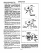
If any parts are missing do not operate your Router until the missing parts are replaced,See Figure 1.
CHIP SHIELD
A clear plastic chip shield is installed on the front of
your router for protection against flying dust and
chips. The chip shield is designed to fit the front
opening of the router base as shown in figure 1. If
necessary to remove, squeeze the tabs on each end
and pull outward. To replace, squeeze the tabs at
each end, fit Into the opening, then release. DO NOT
USE ROUTER WITHOUT CHIP SHIELD PROPERLY
IN PLACE.
SWITCH
The switch of your electronic router is equipped with
a "lock on" feature which is convenient when
operating for extended periods of time. To lock on,
depress the trigger and engage the lock button
located on the side of the handle. To release the
lock, depress the trigger and release it. BE SURE
TOOL IS NOT IN THE "LOCK ON" POBITION
BEFORE CONNECTING TO POWER SUPPLY
SOURCE.
NOTE: If you forget to unlock the tdgger, the "soft"
and "1/4 Inch" Indicator lights will begin flashing
the next time you plug your router into a power
supply source. These flashing lights serve as a
reminder that your trigger is In the "lock on" posi-
tion and that your router will not start until the trig-
ger is relased. The best precaution is to UNLOCK the
trigger after each use.
FRONT
LOCK
HAHDLE
DEPTH LOCK
lUSTING BUTTON
RING
POWER
DEPTH
RING
FRONT_VIEW
-CLAMPING
WING NUT
REAR VIEW
_.COLLET NUT
Fig. 1
Page 4