Owner's Manual 12 in. COMPOUND MITER SAW Double Insulated Model No. 315.212120 Save this manual for future reference. A CAUTION: all Safety Instructions this product. Rules before Read and follow and Operating first use of Customer Help Line: 1-800-932-3188 • Safety • Features • Adjustments • Operation • Maintenance • Parts List Sears, Roebuck and Co., Hoffman Estates, IL 60179 USA Visit the Craftsman web page: www.sears.
TABLE OF CONTENTS Table of Contents.............................................................................................................................................................. 2 Warranty and Introduction............................................................................................................................................. 2 Rules For Safe Operation.........................................................................................................................
RULES FOR SAFE OPERATION The purpose of safety symbols is to attract your attention to possible dangers. The safety symbols, and the explanations with them, deserve your careful attention and uriderstanding. The safety warnings do not by themselves eliminate any |langer. The Instructions or warnings they give are not substitutes for proper accident prevention measures. SYMBOL MEANING ^ SAFETY ALERT SYMBOL: Indicates danger, warning or caution. May be used in conjunction with o№er symbols or pictographs.
RULES FOR SAFE OPERATION (Continued) USE THE PROPER EXTENSION CORD. Make sure your extension cord is in good condition. When using an extension cord, be sure to use one heavy enough to carry the current your product will draw. An undersized cord will cause a drop in line voltage resulting in loss of power and overheating. A wire gage size (A.W.G.) of at least 14 is recommended for an extension cord 25 feet or less in length. If in doubt, use the next heavier gage.
RULES FOR SAFE OPERATION (ContinuecQ ALWAYS SUPPORT LONG WORKPIECES to minimize risk of blade pinching and kickback. Saw may siip, waik, or siide whiie cutting iong or heavy boards. BEFORE MAKING A CUT, BE SURE ALL ADJUSTMENTS ARE SECURE. GUARD AGAINST KICKBACK. Kickback occurs when the biade staiis rapidly and wol1фiece is driven back towards the operator, it can puii your har>d into the biade resuiting in serious personal injury.
RULES FOR SAFE OPERATION (Continued) ■ ALWAYS STAY ALERT! Do not allow familiarity MAKE SURE THE WORK AREA HAS AMPLE LIGHTING to see the work and that no obstruc tions will interfere with safe operaflon BEFORE (gained from frequent use of your saw) to cause a careless mistake. ALWAYS REMEMBER that a careless fraction of a second is sufficient to inflict severe injury. ■ performing any work using your saw.
PRODUCT SPECIFICATIONS Blade Diameter 12 in. Blade Arbor 5/8 in. 4000 RPM No Load Speed Rating Cutting Capacity with Miter at O^/Bevel 0°: max width x resulting height 7-7/8 in. x 2-1/2 in. Maximum Cutting Capacity with Miter at 45°/Bevel 0°: 120 Volts, 60 Hz-AC Only 15 Amperes Input Net Weight max width x resulting height 5-1/2 in. x 2-1/2 in. Maximum Cutting Capacity with Miter at 0°/Bevel 45®: 41 lbs. max width x resulting height 7-7/B in. x 1-3/4 in.
The following labels are on the miter saw with loca tions indicated. Restore lower blade guard and securely tighten screw before use DANGER: DO NOT REMOVE ANY GUARD. USE OF SAW WTTHOUT THEIS GUARD WILL RESULT IN SERIOUS INJURY. AWARNING / ADVERTENCIA • For your sifaty, rud owners manual before operating miter saw. • Wear eye protection. • Keop bands out of path of saw blade. • Do not operala saw without guards In place. • Do not perform any operaHoa freehand. • Nneer reach around the saw blade.
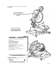
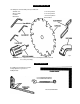
LOOSE PARTS LIST The following items are included with your Compound Miter Saw: Saw Blade -12 in. 5 mm Hex Key Wrench Miter Lock Handle 6 mm Hex Key Wrench Dust Guide 10 mm Hex Key Wrench Blade Wrench Owner's Manual Fig. 2 WARNING: The use of attachments or accessories not listed might be hazardous and could ‘ cause serious personal injury.
FEATURES KNOW YOUR COMPOUND MITER SAW CUTTING CAPACITIES See Figure 3. When the miter angle (miter table) Is set at 0° and the bevel angle Is set at 0°: Before attempting to use your saw, familiarize yourself with all operating features and safety requirements, Your saw will cut materials up to: max width x resulting height 7-7/8 in. x 2-1/2 in. When the miter angle (miter table) Is set at 45° and the bevel angle Is set at 0°: WARNING: Do not allow familiarity with your saw to make you careless.
FEMURES CARRYING HANDLE SPINDLE LOCK BUTTON See Figure 4. See Figure 5. For convenience when carrying or tiwisporting your miter saw from one place to aitother, a carrying handle has been provided on top of the saw arm as shown in figure 4. To transport, turn off and unplug your saw, then lower the saw arm and lock it in the down position. Lock saw arm by depressing the lock pin. A spindle lock button has been provided tor locking the spindle which keeps toe blade in your saw from rotating.
FEATURES POSITIVE STOPS ON MITER TABLE Positive stops have been provided at 0“, 15“, 22-1^, 31.62“, and 45“ on both ttie left and right side of the miter table. BEVEL LOCK KNOB The bevel lock knob securely locks your compound miter saw at desired bevel angles. Positive stop adjustment screws have been provided on each side of the saw arm. These adjustment screws are for making fine adjustments at 0“ and 45°. See pages 18 and 19. ELECTRIC BRAKE Fig.
ADJUSTMENTS TO INSTALL BLADE A WARNING: To prevent accidental starting that could cause possible serious personal injury, assemble all parts to your saw before connecting it to power supply. Saw should never be connected to power supply when you are assembling parts, making adjustments, installing or removing blades, or when not In use. See Figures 10, 11, and 12. WARNING: A12 in. blade is the maximum blade capacity of your saw.
ADJUSTMENTS LOWER BLADE GUARD ARROW ■ Wipe a drop of oil onto inner blade washer and outer blade washer where they contact the blade. A WARNING: If inner blade washer has been renfwved, replace it before placing blade on spindle. Failure to do so could cause an accident since blade will not tighten properly. ■ CAUTION: Always install the blade with the FUT(S) ON SPINDLE blade teeth and the arrow printed on the side of the blade pointing down at the front of the saw.
ADJUSTMENTS Note: Many of the illustrations in this manual show only portions of your compourKi miter saw. This is intentional so that we can clearly show points being made in the illustrations. Never operate your saw without all guards securely in place and in good operating condition. FRAMING SQUARE FENCE CUTTING A SLOT IN THE ZERO CLEARANCE THROAT PLATE In order to use your compound miter saw, you must cut a slot through the zero clearance throat plate to allow for blade cleararrce.
ADJUSTMENTS Using a 6 mm hex key, kx>sen the socket head screws securing the fence. See Figure 16. Adjust the fence ieft or right untii №e framing square and zero ctearanoe throat ptate are paraltei. Retighten the screws secureiy and recheck the fence-to-tabie alignment. 6 mm SOCKET HEAD SCREWS 6 mm SOCKET HEAD SCREWS MITER TABLE MITER LOCK PLATE VIEW OF BLADE SQUARE WITH FENCE MITER LOCK HANDLE Fig. 17 Fig. 16 SQUARING THE SAW BLADE TO THE FENCE See Figures 17-20. ■ Unplug your saw.
ADJUSTMENTS The edge of the square and the saw blade should be parallel as shown in figure 17. Loosen bevel lock knob and set saw arm at 0° bevel (blade set 90° to miter table). Tighten bevel lock knob. If the front or back edge of №e saw blade angles away from the square as shown in figures 18 and 19, adjustments are needed. Place a combination square against the miter table and the flat part of saw blade.
ADJUSTMENTS PIVOT ADJUSTMENTS FENCE Note: These adjustments were made at the factory and normally do not require readjustment. TRAVEL PIVOT ADJUSTMENT ■ The saw arm should rise completely to the up position by itself. ■ If tile saw arm does not raise by itself or if there is play in the pivot joints, have saw repaired by a qualified service technician at your nearest Sears store to avoid risk of personal injury.
ADJUSTMENTS WARNING: Before starting any cutting operation, clamp, bolt or nail your compound miter saw to a workbench. Never operate your miter saw on the floor or in a crouched position. Failure to heed friis warning can result in serious personal injury. CUTTING WITH YOUR COMPOUND MITER SAW A WARNING: When using a work clamp or C-clamp to secure your workpiece, clamp workpiece on one side of the blade only.
OPERATION ■ Slowly lower the blade into and through the workpiece. See Figure 26. . ■ Release the switch trigger and allow the saw blade to stop rotating before raising the blade out of workpiece. Wait until the electric brake stops blade from turning before removing the workpiece from the miter table. BEVEL CUT See Figures 27 and 26. A bevel cut is made by cutting across the grain of the workpiece with the blade angled to the workpiece.
OPERATION WARNING: To avoid serious personal injury, BEVEL CVrr keep your hands outside the no hands zone; at least 3 in. from blade. Never perform any cutting operation freehand (without holding workpiece against toe fence). The blade could grab toe workpiece if it slips or twists. ■ Before turning on the saw, perform a dry run of the cutting operation just to make sure that no problems will occur when the cut is made.
OPERATION TO MAKE A COMPOUND CUT WITH YOUR MITER SAW; ■ Recheck miter angle setting. Make a test cut in scrap material. ■ Pull out the lock pin and lift saw arm to its fuli height. ■ ■ Loosen the miter lock handle. Rotate the miter lock handle approximately one-half turn to the left to loosen. ■ Press the miter iock piate down with your thumb and hold. Place the workpiece flat on the miter table with one edge securely against the fence.
OPERATION ■ ■ ■ ■ Before turning on the saw, perform a dry run of the cutting (^ration just to make sure that no problems will occur when the cut is made. Grasp the saw handle firmly, press the lock-off tab down, then squeeze the switch trigger. Allow sev eral seconds for the blade to reach maximum speed. Slowly lower the blade into and through the workpiece. See Figures 29 and 30. Release №e switch trigger and allow the saw blade to stop rotating before raising the blade out of workpiece.
OPERATION CUTTING COMPOUND MITERS To aid in making the correct settings, the compound angle setting chart below has been provided. Since com pound cuts are the most difficult to accurately obtain, trial cuts should be made in scrap material, and much thought and planning made, prior to making your required cut. PITCH 0F9DE ■ nUMDCn 4 5 MT 6 7 8 9 0° M- 45.00' M- 36.00' B- 0.00' B- 0.00' M- 30.00' B- 0.00' M- 25.71° B- 0.00' M- 22.50° B- 0.00' M- 20.00' B- 0.00° M-18.00' B- 0.00° 5“ M- 44.
OPERATION CUTTING CROWN MOLDING LAYING MOLDING FLAT ON THE MITER TABLE Your compound miter saw does an excellent job of cutting crown molding. In gerreral, compound miter saws do a better job of cutting crown molding than any other tool made. See Figure 32. To use this method for accurately cutting crown molding for a 90° inside or outside comer, lay the molding with its broad back surface flat on the miter table and against the fence.
OPERATION When cutting crown molding by this method the bevel angle should be set at 33.85°. The miter angle should be set at 31.62° either right or left, depending on the desired cut for the application. See the chart below for correct angle settings and correct positioning of crown molding on miter table. The settings in the chart below can be used for cutting All Standard (U.S.) crown molding with 52° and 38° angles.
MAINTENANCE EXTENSION CORDS WARNING: When servicing, use only identicat Craftsman replacement parts. Use of any other part may create a hazard or cause product damage. The use of any extension cord will cause some loss of power. To keep the loss to a minimum and to prevent tool overheating, use an extension cord that is heavy enough to carry the current the tool will draw. GENERAL A wire gage size (A. W.G.) of at least 14 is recom mended for an extension cord 25 feet or less in length.
MAINTENANCE iW WARNING; To ensure safety and reliability, all Your saw has externally accessible brush assemblies that should be periodicaiiy checked for wear. repairs — with the exception of the externally accessible brushes — should be performed by a qualified service technician at a Sears store to avoid risk of personal injury. Proceed as follovro when replacement is required: ■ WARNING: Failure to unplug your saw could BRUSH REPLACEMENT See Figure 36.
CRAFTSMAN COMPOUND MITER SAW - MODEL NUMBER 315.
CRAFTSMAN COMPOUND MITER SAW - MODEL NUMBER 315.212120 The model number will be found on a plate attached to the motor housing. Always mention the model number in all correspondence regarding your COMPOUND MITER SAW or when ordering repair parts. SEE BACK PAGE FOR PARTS ORDERING INSTRUCTIONS PARTS LIST FOR FIGURE A KEY NO. 1 PART NUMBER DESCRIPTION 976512-001 Flat Washer............................................................................................ ........... 2 QUAN.
CRAFTSMAN COMPOUND MITER SAW - MODEL NUMBER 315.
CRAFTSMAN COMPOUND MITER SAW - MODEL NUMBER 315.212120 The model number will be found on a plate attached to the motor housing. Always mention the model number in all correspondence regarding your COMPOUND MITER SAW or when ordering repair parts. SEE BACK PAGE FOR PARTS ORDERING INSTRUCTIONS KEY PART NO.
CRAFTSMAN COMPOUND MITER SAW - MODEL NUMBER 315.
CRAFTSMAN COMPOUND MiTER SAW - MODEL NUMBER 315.212120 The model number will be found on a plate attached to the motor housing. Always mention the model number in all correspondence regarding your COMPOUND’MITER SAW or when ordering repair parts. SEE BACK PAGE FOR PARTS ORDERING INSTRUCTIONS PARTS LIST FOR FIGURE C Key No.
For in-home major brand repair service: Call 24 hours a day, 7 days a week 1-800-4-MY-Home®« (1-800-469-4663) Para pedir servicio de reparación a domiciiio -1-800-676-5811 in Canada for all your service and parts needs call _ ^ Au Canada pour tout le service ou les pièces ' 665-4455 ' For the repair or replacement parts you need: Call 7 am - 7 pm, 7 days a week 1-800-366-PART (1-800-366-7278) Para ordenar piezas con entrega a domiciiio -1-800-659-7084 For the location of a Sears Parts and Repair Center