
User guide


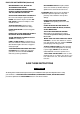


Table Of Contents
- TABLE OF CONTENTS
- WARRANTY
- INTRODUCTION
- RULES FOR SAFE OPERATION
- SAVE THESE INSTRUCTIONS
- A WARNING / ADVERTENCIA
- OFF
- WARNING^
- ADVERTENCIA
- FEATURES
- KNOW YOUR BAND SAW
- BLADE
- BLADE GUIDES '
- BLADE GUIDE KNOB AND LOCK LEVER
- TABLE LOCK KNOB
- ANGLE ADJUSTMENT KNOB
- SCALE
- TENSION ADJUSTMENT KNOB
- TRACKING ADJUSTMENT SCREW
- BAND SAW TABLE
- SAWDUST EXHAUST PORT
- COVER TABS
- HEX KEY HOLDER
- ON/OFF KNOB
- INSTALLING SCALE INDICATOR
- INSTALLING THE TABLE
- MOUNTING BAND SAW TO WORKBENCH
- CLAMPING BAND SAW TO WORKBENCH
- ADJUSTMENTS
- BASIC OPERATION
- MAINTENANCE
- 1 -800-4-MY-Home®“ (1-800-469-4663)
- 1-800-488-1222
- 1-800-827-6655
UNPACKING
WARNING: To prevent accidental starting that
could cause possible serious personal injury,
assemble all parts to your saw before connecting
it to power supply. Saw should never be
connected to power supply when you are
assembling parts, making adjustments, installing
or removing blades, or when not in use. ,
Carefully remove all parts from the carton and
place the saw on a level work surface. Separate
and check against the list of loose parts.
iV WARNING: If any parts are missing, do not
operate this tool until the missing parts are
replaced. Failure to do so could result In possible
serious personal injury.
■ Do not discard the packing materials until you
have carefully inspected the saw, identified all
parts, and satisfactorily operated your new saw.
Note: If any parts are damaged or missing, do not
attempt to plug in the power cord and turn the switch
on until the damaged or missing parts are obtained
and are installed correctly.
LOOSE PARTS LIST
ymm ^
Check all loose parts from the box with the list below. For your convenience when identifying parts, items A-H
below have been drawn actual size. Assemble according to the instructions on the following pages.
A. Flat Head Screw (1/4-20 x 7/8 in.).................................3
B. Hex Nut (1/4-20)
.............................................................
3
C. Wing Nut (1/4-20)...........................................................1
D. Truss Head Screw (1/4-20 x 5/8 in.)
.............................
1
E. Screw (M5 x 8)...............................................................1
F. Scale Indicator
..............................................................
1
G. Throat Plate
...................................................................
1
H. Hex Key (1/8 in.)
............................................................
1
I. Saw Table (not shown)
.................................................
1
J. Owner's Manual (not shown)
.......................................
1
Fig. 2
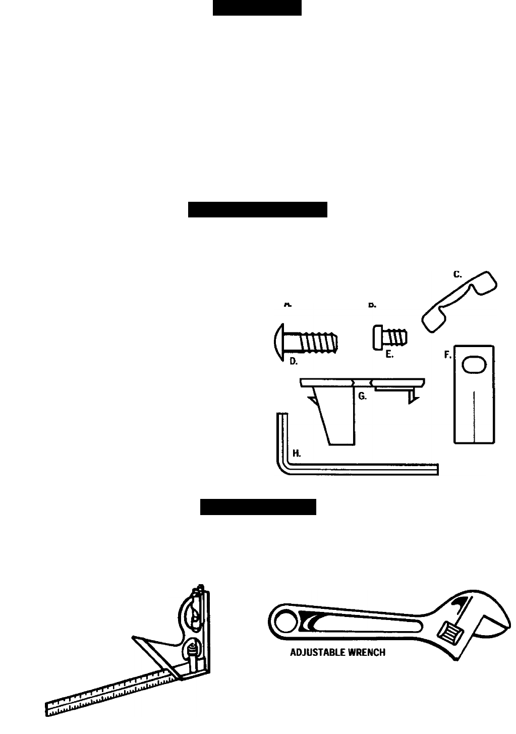
TOOLS NEEDED
The following tools (not included) are needed for
assembly and alignment:
• #2 Phillips Screwdriver
• Adjustable Wrench
■ Small Combination Square
• 5/16 in. Socket or Nut Driver
SMALL
COMBINATION
SQUARE
#2 PHILUPS SCREWDRIVER
&
5/16 in. SOCKET/NUT DRIVER
Fig. 3