
Manual


ASSEMBLY
■ Get the front rail pieces, the switch assembly, and
the following hardware;
6 square head bolts (5/16-18 x 1 in.)
6 flat washers (5/16 in.)
6 hex nuts (5/16-18)
2 screws (1/4-20 x 3/8 in.) (located on switch plate)
2 square nuts (1/4-20) (located on switch plate)
Front rail connector
Right and left end caps for front rail
2 screws (#8-32 x 1/2 in.)
■ Set aside end caps and screws until you have
aligned the rip fence and front rail.
■ Insert the six square head bolts into the table and
extensions, so the bolt heads extend outward 1/2 in.
■ Loosely attach a washer and a hex nut to each
bolt.
■ The back of the rail has two slots. Slide the upper
slot over the bolts. (Bottom slot is for switch.)
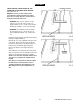
■ Align the right rail from left to right - Match the
7-1/8 in. mark on the right scale to the right
edge of the table saw base (main table). See
Figure 16.
■ Snug right rail against table. Finger-tighten each
nut on the table and extensions.
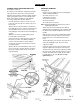
■ Locate the switch assembly. The two screws are
installed through the back of the switch plate with
the square nuts extending out toward the front.
Note: The square nuts are loose on the switch plate.
■ Slide the square nuts into the lower slot of the rail,
■ Slide the switch assembly to a convenient position,
leaving ample clearance for the handwheel.
Tighten securely with a screwdriver. Do not tighten
the rail bolts.
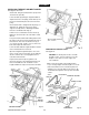
■ Attach the end caps and screws with a phillips
screwdriver.
iV WARNING: Place the switch out of the
immediate work area to avoid accidentally
turning it off during operation.
SAW TABLE
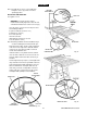
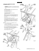
INSTALLING THE FRONT RAIL
See Figures 15 and 16.
SQUARE
HEAD BOLTS
TABLE
EXTENSION
HEX NUT
FRONT RAIL
CONNECTOR
Fig. 15
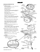
FRONT RAIL
END CAP
7-1/8 in. MARK
RIGHT SCALE
CRRFTSMnrTABLE SAW 315.228390
FRONT RAIL
Fig. 16
22