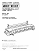
OPERATOR'S MANUAL II:RRFTSMRN I ROUTER DOVETAIL JOINT TEMPLATE KIT MODEL NO. 315.25791 FOR USE WITH ROUTERS WITH 3-HOLE TEMPLATE GUIDE MOUNT, _ WARNING: To reduce the risk of injury, the user must read and understand the operator's manual before using this product. Customer Help Line: t-800-932-3188 Sears, Roebuck and Co., 3333 Beverly Rd., Hoffman Visit the Craftsman web page: www.sears.
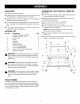
• Introduction ..................................................................................................................................................................... 2 • General Safety Rules ....................................................................................................................................................... 3 • Symbols .......................................................................................................................................
_L • ARNING: read and understand all instructions. Failure to follow all instructions listed below, may result in electric shock, fire and/or serious personal injury. • SAVE THESE INSTRUCTIONS • Read these instructions and the instructions for your router thoroughly before using accessory. • Know your power tool. Read the operator's manual for your router carefully. Learn the router's app(ications and limitations as well as the specific potential hazards related to this tool.
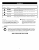
Thefollowingsignalwordsandmeanings areintendedto explainthe levelsofriskassociated withthisproduct. SYMBOL SIGNAL MEANING ,_ DANGER: Indicates an imminently hazardous situation, which, if not avoided, will result in death or serious injury. _k WARNING: Indicates a potentially hazardous situation, which, if not avoided, could result in death or serious injury. ,_ CAUTION: Indicates a potentially hazardous situation, which, if not avoided, may result in minor or moderate injury.
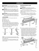
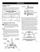
UNPACKING ASSEMBLING This product requires assembly. See Figure 1. • Carefully remove all parts from the box. Make sure that all items listed in the packing list are included. • Insert hex bolts through holes located at top and front of dovetail base as shown in figure 1. • Inspect the parts carefully to make sure no breakage or damage occurred during shipping. • Make sure the bolt head flats are lined up with slots inside the dovetail base.
_ WARNING: Do not allow familiarity with tools to make you careless. Remember that a careless fraction of a second is sufficient to inflict serious _ A MOUNTING DOVETAIL BASE See Figures 3 - 4. injury. _ WARNING: Always wear safety goggles or safety glasses with side shields when operating power tools. Failure to do so could result in objects being thrown into your eyes resulting in possible serious injury.
INSTALLING TEMPLATE AND CUTTER GUIDE BUSHING See Figure 5. Two template guide bushings are supplied with the router dovetail template kit. They are used to guide the router in and out of the fingers of the comb-shaped template. The 5/16 in. bushing is used when making 1/4 in. dovetails, while the 7/16 in. bushing is used when making 1/2 in. dovetails. _ CLAMP WARNING: To avoid possible serious personal injury, unplug the router while assembling parts or making adjustments.
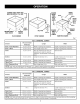
DRAWERHEIGHTFRONTAND BACKSIDE WIDTH 12 in. MAX. DRAWER HEIGHT BACK WIDTH SIDE WIDTH FRONT LENGTH 3/8 in. 3R in. FRONT WIDTH MAX. 3_ in. SIDE LENGTH DRAWERWIDTH BACKLENGTH DRAWER LENGTH HALF-PIN 1/16 in. FLUSH DRAWER DRAWER LENGTH DRAWER WIDTH BACK LENGTH OFFSETDRAWER SIDE LENGTH RABBETEDDRAWER Fig, 7 1/2 in. DOVETAIL JOINTS Recommended Section Length Thickness Width Back - Flush/Rabbeted 1/2 in. to 3/4 in.
REFERENCE GUIDE See Figure 8. The base of the router dovetail template kit has a label to serve as a guide for you to follow when making set-ups for different types of joinery. Familiarize yourself with this label and refer to it as often as necessary. DOVETAIL 1/2 in. Tails JOINT _ BRACKET LOCATION BIT DEPTH FLUSH A A 1 17/32 in. OFFSET A A 2 _ABBETED R A 3 I JOINT STOP 1/4 in. Tails _STOP I TOP ISlUEI BRACKET LOCATION I BfT DEPTH FLUSH C C 1 7/16 in. 17/32 in.
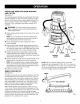
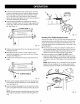
• Insertboard(A)betweenfrontclampingbarandfront surfaceof dovetailbasewithbottomedgetowardthe left2-waystop.Temporarily clampboard(A)"insideout"to theleftfrontofthefixtureso thatit extends abovethebase.See Figure 12. This is done to assist in the proper positioning of board (B). • Insert board (B) between top clamping bar and top surface of dovetail base, with bottom edge against left 3-way stop, and flush with extended portion of board (A). See Figure 12. CLAMPINGKNOB(E) H G G Fig.
,_ Youarenowreadyto routyoursecondflushdovetailjoint. Doso by repeating theaboveprocedure withboards(C) and(B)positionedagainsttherightstops.See Figure 16. WARNING:Usecaution whenoperating routerat eitherextremeendof dovetail template.Thedovetail cutterwill makecontactwithanglebracketif movedtoofaroutsidefirstor finalcut. • Cutthedovetailjoint.Feedthe routerinandouteach finger,movingfromleftto right. • Recutthedovetailmovingtherouterfromrightto left.
OFFSET-FRONT ,_ • Loosen the stop screws on your dovetail base and place the 3 way stop on top and the 2 way stop on the side in their proper position. See Figures 8 and 20. Retighten stop screws securely. DRAWER WARNING: Unplug router from power supply while assembling parts or making adjustments. Failure to do so could result in accidental starting of the router causing damage to the work surface or possible serious personal injury.
• Insertboard(A)betweenfrontclampingbarandfront surfaceof dovetailbasewithbottomedgetowardthe left2-waystop.Temporarily clampboard(A)"insideout"to theleftfrontofthefixtureso thatit extends abovethebase.See Figure 22. This is done to assist in the proper positioning of board (B). • Insert board (B) between top clamping bar and top surface of dovetail base, with bottom edge against left 3-way stop, and flush with extended portion of board (A). See Figure 22. CLAMPINGKNOB(E) H Fig.
_ Youarenowreadyto routyoursecondoffsetdovetail joint.Doso byrepeating the aboveprocedure withboards (C)and(B)positionedagainsttherightstops. ARNING:Usecaution whenoperating routerat eitherextreme endofdovetail template.Thedovetailcutterwillmakecontactwithanglebracketif movedtoo faroutsidefirstorfinalcut. See Figure 26. • Cutthedovetailjoint.Feedthe routerinandouteach finger,movingfromleftto right. • Recutthedovetailmovingthe routerfromrightto left.
RABBETED FRONT DRAWER 3 WAY STOP ,_ WARNING: Unplug router from power supply while assembling parts or making adjustments. Failure to do so could result in accidental starting of the router causing damage to the work surface or possible serious personal injury. A rabbeted front drawer is used when you want the drawer front to overlap the top, bottom, and both sides of the drawer opening. The drawer front is both 3/4 in. wider than the drawer sides and 3/4 in. longer than the drawer width.
• Insertboard(A)betweenfrontclampingbarandfront surfaceof dovetailbasewithbottomedgetowardthe left2-waystop.Temporarily clampboard(A)"insideout"to theleftfrontofthefixtureso thatit extends abovethebase.See Figure 32. This is done to assist in the proper positioning of the board (B). • Insert board (B) between top clamping bar and top surface of dovetail base, with bottom edge against left 3-way stop, and flush with extended portion of board (A). See Figure 32. G CLAMPINGKNOB(E) G H Fig.
• Cutyourdovetailjoint.Feedtherouterinandouteach finger,movingfromleftto right. • Recutthedovetailmovingtherouterfromrightto left. Thiswillcleanoffanyspotsor imperfections thatmight havebeenmissed. • Waituntilthecutterhascompletelystoppedbefore removingtherouter.Thiswillpreventpossibleserious injuryoranydamagetothe dovetailtemplate.When removingtherouter,it shouldnotbeliftedbutshould bemovedtowardtheoperatoruntilclear. • Checkto makesureyouhaveroutedeachdovetail evenly.
HELPFUL HINTS • Don't let familiarity make you careless. • Always bevel the drawer front for an offset-front drawer. • Always clamp workpiece securely for cutting. • Study all safety rules and do the job safely. • • Plan your drawer height opening so that the boards will be in increments of 7/8 in. for 1/2 in. joints, or 29/64 in. increments for 1/4 in. joints. This will allow a half-pin to be on both the top and bottom edge of the drawer front. Don't forget to allow for clearances.
CRAFTSMAN PRODUCT NAME - MODEL NUMBER 315.25791 [ The model number will be found on a plate attached to the motor housing. Always mention the model number in all correspondence regarding your accessory or when ordering repair parts. SEE BACK PAGE FOR PARTS ORDERING I" _ 2 INSTRUCTIONS I" ,_3 I 9 / f t 16 2 17 I 19 3 * Standard Hardware Item - May Be Purchased Locally ** Available From Div. 98 - Source 980.
CRAFTSMAN I PRODUCT NAME - MODEL NUMBER 315.25791 ] The model number will be found on a label attached to the base. Always mention the model number in all correspondence regarding your accessory or when ordering repair parts. SEE BACK PAGE FOR PARTS ORDERING INSTRUCTIONS PARTS LIST Key No. Part Number Description 1 000900067001 Clamping Knob ............................................................................................... 2 000900067002 Washer ................................