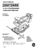
Owner's Manual 5-1/2 in. PROFESSIONAL CORDLESS TRIM SAW Sears, Roebuck and Co., Hoffman Estates, IL 60179 USA Visit the Craftsman web page: www.sears.
TABLE OF CONTENTS ■ Table of Contents...............................................................................................................................................2 ■ Warranty and Introduction...... .................................................................................................................. ......... 2 ■ Rules For Safe Operation............................ ................. .................................................................................. 3-5 A.
RULES FOR SAFE OPERATION The purpose of safety symbols is to attract your attention to possible dangers. The safety symbols, and the explanations with them, deserve your careful attention and understanding. The safety warnings do not by themseives eliminate any danger. The instructions or warnings they give are not substitutes for proper accident prevention measures. SYMBOL MEANING A SAFETY ALERT SYMBOL: A DANGER: Failure to obey a safety warning will result in serious injury to yourself or to others.
RULES FOR SAFE OPERATION (Continued) ■ MAINTAIN TOOLS WITH CARE. Keep tools sharp at all times, and clean for best and safest performance. Follow instructions for lubricating and changing accessories. ■ REMOVE ADJUSTING KEYS AND WRENCHES. Form habit of checking to see that keys and adjusting wrenches are removed from tool before turning it on. ■ NEVER USE IN AN EXPLOSIVE ATMO SPHERE. Normal sparking of the motor could ignite flammable liquids, gases, or fumes.
RULES FOR SAFE OPERATION (Continued) ■ ■ Make sure cord is located so that it will not be stepped on, tripped over, or otherwise subjected to damage or stress. An extension cord should not be used unless absolutely necessary. Use of improper extension cord could result in a risk of fire and electric shock. If extension cord must be used, make sure: a. That pins on plug of extension cord are the same number, size and shape as those of plug on charger. b.
PRODUCT SPECIFICATIONS Blade Diameter Blade Arbor Cutting Depth at 0° Bevel Cut Cutting Depth at 45° Bevel Cut 5-1/2 in. No Load Speed Motor 3/8 in. 1-9/16 in. 3,800 RPM 14.4 Volts DC Charge Rate 1-1/8 in. Charger Rating 1 Hour 120 volts, 60 Hz, AC UNPACKING Your trim saw has been shipped completely assembled except for the blade. Inspect it carefully to make sure no breakage or damage has occurred during shipping.
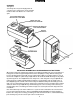
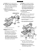
FEATURES CHARGER See Figure 2. Your charger has a "key hole" hanging feature for convenient, space saving storage. Screws should be installed so that center distances are 1-7/16 inches apart. ■ YELLOW AND GREEN LIGHT INDICATE SOFT START MODE GREEN LIGHT "ON" INDICATES FUaV CHARGED REDUGHT"ON" INDICATES FAST CHARGING MODE BATTERY CHARGER BACKSIDE OF CHARGER Fig. 2 IMPORTANT INFORMATION FOR RECHARGING HOT BATTERIES When using your trim saw continuously, the batteries in your battery pack will become hot.
FEATURES SWITCH See Figure 2. KNOW YOUR TRIM SAW See Figure 2. Before attempting to use any tool familiarize yourself with all operating features and safety requirements. Your saw is equipped with a lock-off button which reduces the possibility of accidental starting. The lockoff button is located on the handle above the switch trigger. You must depress the lock-off button in order to pull the switch trigger. The lock resets each time the trigger is released.
OPERATION WARNING: Always wear safety goggles or safety glasses with side shields when operating tools. Failure to do so could result in objects being thrown into your eyes, resulting in possible serious injury. WARNING: Do not allow familiarity with your trim saw to make you careless. Remember that a careless fraction of a second is sufficient to inflict severe injury, CHARGING YOUR TRIM SAW The battery pack for this tool has been shipped in a low charge condition to prevent possible problems.
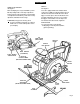
OPERATION A. WARNING: A 5-1/2 in. blade is the maximum blade capacity of your saw. Never use a blade that is too thick to allow outer blade washer to engage with the flats on the spindle. Larger blades will come in contact with the blade guard, while thicker blades will prevent blade screw from securing blade on spindle. Either of these situations could result in a serious accident. A.
OPERATION SAW BLADES ■ Fit saw blade inside lower blade guard and onto spindle. Note: The saw teeth point upward at the front of saw as shown in figure 4. The best of saw blades will not cut efficiently if they are not kept clean, sharp, and properly set. Using a dull blade will place a heavy load on your saw and Increase the danger of kickback. Keep extra blades on hand, so that sharp blades are always available. ■ Replace outer blade washer. ■ Depress spindle lock button, then replace blade screw.
OPERATION KICKBACK See Figure 7. TO LESSEN THE CHANCE OF KICKBACK: ■ Always keep the correct blade depth setting - the correct blade depth setting for all cuts should not exceed 1/4 in. below the material to be cut. See Figure 9. One blade tooth below the material to be cut works best for most efficient cutting action. KICKBACK BLADE SET TOO DEEP Fig. 7 The best guard against kickback is to avoid dangerous practices. Kickback occurs when the blade stalls rapidly and the saw is driven back towards you.
OPERATION ■ When making a cut use steady, even pressure. Never force cuts. STARTING A CUT Know the right way to use your saw. ■ Do not cut warped or wet lumber. ■ Always hold your saw firmly with both hands and keep your body in a balanced position so as to resist the forces of kickback should it occur. When using your saw, always stay alert and exercise control. Do not remove your saw from workpiece white the blade is moving. DEPTH OF CUT ADJUSTMENT Always keep correct blade depth setting.
OPERATION TO HELP MAINTAIN CONTROL; ■ Always support your workpiece near the cut. ■ Support your workpiece so the cut will be on your left. ■ Clamp your workpiece so it will not move during the cut. Place your workpiece with its good side down. Note: The good side is the side on which appearance is important. Before beginning a cut, draw a guideline along the desired line of cut. Then place front edge of base on that part of your workpiece that is solidily supported. See Figure 12.
OPERATION RIP GUIDE (EDGE GUIDE) TOP VIEW OF SAW GUIDEUNE Use the rip guide provided with your saw when making wide rip cuts. A five inch scale has been provided on the rip guide. When using the width of cut scale on the base in combination with the rip guide, cuts can be made up to 6 in. to the left of the blade or 8-3/4 in. to the right of the blade. The rip guide helps prevent the blade from twisting in a cut. The blade twisting in a cut can cause kickback.
OPERATION When making a bevel cut hold your saw firmly with both hands as shown in figure 20. TO BEVEL CUT The angle of cut of your saw may be adjusted to any desired setting between zero and 50°. Note: When making cuts at 50°, blade should be set at full depth of cut. When making 45° bevel cuts, there is a notch in the saw base to help you line up the blade with the tine of cut. See Figure 19. Rest the front edge of the base on the workpiece.
OPERATION POSITIVE 0° BEVEL STOP See Figure 21. ■ Turn screw and adjust base until square with saw blade. ■ Tighten hex nut and bevel adjustment knob securely. ADJUSTMENT SCREW BEVEL ADJUSTMENT KNOB .A WARNING: Attempting to make cuts without bevel adjustment knob securely tightened can result in serious injury. TO POCKET CUT See Figure 22. HEX NUT BLADE A WARNING: Always adjust bevel setting to zero before making a pocket cut.
MAINTENANCE Do not abuse power tools. Abusive practices can damage tool as well as workpiece. A WARNING; When servicing, use only identical Craftsman replacement parts. Use of any other . part may create a hazard or cause product damage. Only the parts shown on parts list, page twenty one, are intended to be repaired or replaced by the customer. All other parts should be replaced by a qualified service technician at an authorized service facility. Avoid using solvents when cleaning plastic parts.
CRAFTSMAN CORDLESS TRIM SAW - MODEL NUMBER 315.
CRAFTSMAN CORDLESS TRIM SAW - MODEL NUMBER 315.269600 The model number will be found on a plate attached to the motor housing. Always mention the model number in all correspondence regarding your CORDLESS TRIM SAW or when ordering repair parts. SEE BACK PAGE FOR PARTS ORDERING INSTRUCTIONS PARTS LIST Key No. Part Number Carriage Bolt (M6 x 102 mm)................ ............. 1 16 975541-000 Bumper Screw..................................... ............. 1 975547-000 Base Assembly.................
For in-home major brand repair service: Call 24 hours a day, 7 days a week 1-800-4-MY-Home™ (1-800-469-4663) Para pedir servicio de reparación a domicilio -1-800-676-5811 In Canada for all your service and parts needs call . ^лл с е в л л в в j •I" -1-800-665-4455 Au Canada pour tout le service ou les pieces For the repair or replacement parts you need: Call 7 am - 7 pm, 7 days a week 1-800-366-PART (1-800-366-7278) Para ordenar piezas con entrdga a domicilio -1-800-659-7084.