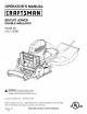
OPERATOR'S MANUAL II:RRFTSMRN I BISCUIT JOINER DOUBLE INSULATED Model No. 315.175390 ,_ WARNING: To reduce the risk of injury, the user must read and understand the operator's manual before using this product. Customer Help Line: t-800-932-3188 Sears, Roebuck and Co., 3333 Beverly Rd., Hoffman Visit the Craftsman web page: www.sears.
• Warranty .......................................................................................................................................................................... 2 • Introduction ..................................................................................................................................................................... 2 • General Safety Rules ...................................................................................................................
_L ARNING: Read and understand all instructions. Failure to follow all instructions listed below, may result in electric shock, fire and/or serious personal injury. • Avoid accidental starting. Be sure switch is off before plugging in. Carrying tools with your finger on the switch or plugging in tools that have the switch on invites accidents. • Remove adjusting keys or wrenches before turning the tool on.
SERVICE • • Tool service must be performed only by qualified repair personnel. Service or maintenance performed by unqualified personnel may result in a risk of injury. • Hold tool by insulated gripping surfaces when performing an operation where the cutting tool may contact hidden wiring or its own cord. Contact with a "live" wire will make exposed metal parts of the cutting tool "live" and shock the operator. • Know your power tool. Read operator's manual carefully.
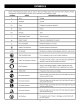
Someof the followingsymbolsmaybe usedonthis tool. Pleasestudythemandlearntheirmeaning.Proper interpretation ofthesesymbolswillallowyouto operatethetool betterandsafer.
Thefollowingsignalwordsandmeanings areintendedto explainthe levelsofriskassociatedwiththisproduct. SYMBOL SIGNAL MEANING ,_ DANGER: Indicates an imminently hazardous situation, which, if not avoided, will result in death or serious injury. _k WARNING: Indicates a potentially hazardous situation, which, if not avoided, could result in death or serious injury. ,_ CAUTION: Indicates a potentially hazardous situation, which, if not avoided, may result in minor or moderate injury.
DOUBLE INSULATION Double insulation is a concept in safety in electric power tools, which eliminates the need for the usual three-wire grounded power cord. All exposed metal parts are isolated from the internal metal motor components with protecting insulation. Double insulated tools do not need to be grounded. _ WARNING: The double insulated system is intended to protect the user from shock resulting from a break in the tool's internal insulation.
PRODUCT SPECIFICATIONS Fence Angle Adjustments ....................................... Depth of Cut ........................................................ 0-135 ° 0-9/16 in. Cord Length ............................................................... Blade ........................................................................... 10 ft. 4 in. No Load Speed ............................................... Input ............................... 120 V, 60 Hz, AC only, 6.0 Amps Net Weight ...........
KNOW YOUR BISCUIT JOINER DUAL GRIP HANDLE See Figure 1. Before attempting to use this product, familiarize yourself with all operating features and safety rules. SWITCH TRIGGER The biscuit joiner has a conveniently located ON/OFF switch trigger on the underside of the dual grip handle. CARBIDE-TIPPED BLADE The biscuit joiner has an 8-tooth carbide-tipped cutting biscuit slots.
UNPACKING INSTALLING/REMOVING This product requires assembly. See Figure 2. • Carefully remove the tool and any accessories from the box. Make sure that all items listed in the packing list are included. • Inspect the tool carefully to make sure no breakage or damage occurred during shipping. The dust bag located on the rear of the biscuit joiner provides a dust collection system. Wood particles are drawn up through the base and collect in the dust bag during cutting operations.
_ When joining 1-1/2 in. thick materials, stack two biscuits, one above the other. For example, use this method when joining 2 in. x 4 in. dressed lumber. When joining even thicker materials, use additional biscuits, stacked above each other. WARNING: Do not allow familiarity with tools to make you careless. Remember that a careless fraction of a second is sufficient to inflict serious injury. ,_k When making edge-to-edge joints for tabletops, workbenches, cutting boards, etc.
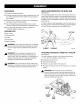
DEPTH OF CUT MAKING The biscuit joiner can be adjusted to three standard cutting depths to accommodate three standard size biscuits -- #0, #10, and #20. Adjustments are made by engaging slots on the depth adjustment knob with tabs on the rear base assembly. For example, when using a #0 size biscuit, rotate the depth adjustment knob to the slot marked 0.
FENCE FENCE ANGLE HEIGHT The adjustable fence on the biscuit joiner can be moved up or down to adjust the position of the blade in relation to the top of the workpiece. A scale on each side of the fence indicates the height of the fence from the center of the blade. The fence can be positioned up to two inches from the center of the blade. However, the scale and indicator point can only be set up to 2 in. from the center of the blade. Scale marks are in increments of 1/16 in.
MAKING EDGE-TO-EDGE JOINTS CENTERLINE MARKS See Figures 9 - 10. Edge-to-edge joinery is one of the most basic and easilyconstructed joints. • Unplug the biscuit joiner. • Prepare the workpieces by laying them side by side on a workbench in the order in which they will be assembled. • Using a square, determine the location of each biscuit spline joint and mark the center of each joint by drawing a line across each workpiece. NOTE: Mark the edges 2 in. from the ends of the workpieces.
BUTTJOINTS BUTT JOINTS A butt joint is made by mating the end grain of one board with the edge grain of another. The bonding of glue on this type of surface is poor. However, by using biscuits you can create a strong joint that gives a mortise-andtenon effect. MAKING BISCUIT SLOT(S) BUTT JOINTS UIT(S) See Figures 11 - 12. • Unplug the biscuit joiner. • Place the two pieces of wood to be joined on a level workbench. Align them against each other in the arrangement in which they will be assembled.
T- JOINTS • Set the fence angle at 90 ° See Figure 13. • Set the fence height at the desired dimension on the scale. • Select the correct depth of cut setting for the biscuit size you plan to use. • Clamp the workpiece securely, then cut each slot at the marked centerline intersection. A T-joint is used when the end of a board is joined to the face of another board. Attaching shelves to bookcases and inner support braces to frames are typical applications.
CUTTING VERTICAL HEIGHT ADJUSTMENT KNOB BOARDS See Figures 16- 17. • Unplug the biscuit joiner. • Loosen the locking knob and set the fence angle at 0°. • Set the fence height at the desired dimension on the scale by rotating the height adjustment knob. • Retighten the locking knob. • Select the correct depth of cut setting for the biscuit size you plan to use. • Clamp the workpiece securely. • Cut each slot at the marked centerline intersection.
MITER JOINTS • There are two types of miter joints that can be made using biscuits: flat miters and edge miters. Fiat miters are used when making picture frames. Edge miters are used when making boxes or things where you don't want to show the end grain of the wood. Finally, disassemble the workpieces and place a bead of glue in each slot. Also, spread a bead of glue over the entire surface of the joint. Reinsert the biscuits and assemble the workpieces.
• Placethebiscuitjoinerontheworkpiecewiththe adjustablefencerestingonthelongsideof workpiece. Thebaseor verticalfenceshouldbeagainstthemiterededgeoftheworkpiece. • Recheckthefenceheightsettingto makesureit will notcutthroughthe workpiece. • Aligntheindicatormarkonthefencewiththe centerlineontheworkpiece.Makesurethe baseor vertical fenceis pressedflatagainstthemiterededgeofthe workpiece. • Plugthebiscuitjoinerintothepowersupplyandprepareto cutthe slot.
_k _k REPLACING WARNING: When servicing, use only identical Craftsman replacement parts. Use of any other parts may create a hazard or cause product damage. After extended use, the blade on your biscuit joiner may become dull and need replacing. If you accidentally hit a nail or other blunt object, it will break the carbide tips, which will require replacing the blade. WARNING: Always wear safety goggles or safety glasses with side shields during power tool operation or when blowing dust.
• Placea screwdriver inthe holeprovidedinthebearing plate. • Placeoneofthenon-cuttingteethlocatedbehindeach carbide-tipped cuttingtoothagainstthescrewdriver or pinandlockthebladeto preventit fromrotating.DO NOTlockthebladeagainstoneofthe cuttingteeth. Carbidetips willbreak. • Usinga 3/16in. hexkey,removethe bladescrew. NOTE:Turnthe bladescrewcounterclockwise to removethe blade. SCREWDRIVER • Remove the outer blade washer, blade and inner blade washer.
CLEANING PATH THE BASE ASSEMBLY SHOWNWITHOUTDUSTBAG AND DUST SCREW(S) SHOE See Figures 25 - 27. After extended use, wood particles and resin may build up inside the base assembly of your biscuit joiner and clog the path for wood particles going into dust bag. Wood particles packing up in this area not only defeats the dustless feature of your biscuit joiner, it also makes cutting biscuit slots more difficult. • Unplug the biscuit joiner. • Remove the dust bag.
• Usinga screwdriver, removethetwoscrewsthatconnectthefrontandrearbaseassemblies. • Carefully separatethefrontbaseassemblyfromthe rearbaseassembly.Remove thefrontbaseassembly. NOTE:Thesepiecesaretightlyjoined.It maybehelpful to usea malletto lightlytapthe areawherethe assemblies meet. • Removetherearbaseassembly. • Withtheassemblies separated, cleanwoodparticles andresinfromthe bladearea,dustbagport,frontand rearassemblies andallsurrounding areas.
Thefollowingrecommended accessories arecurrentlyavailable at Searsretailstores: • Biscuits100pieces............................................................................................................................................. Size0 • Biscuits100pieces............................................................................................................................................. Size10 • Biscuits100pieces..............................................................................
• CRAFTSMAN BISCUIT JOINER - MODEL NUMBER 315.175390 • SEE NOTE 9 8 27 37 28 39 32 30 31 23 32 30 i 19_ 25 24 24 42 42 21 _22 NOTE: The assembly shown represents an important part of the Double Insulated System. To avoid the possibility of alteration or damage to the System, service should be performed by your nearest Sears Repair Center. Contact your nearest Sears Retail Store for Service Center information.
_- CRAFTSMAN l BiSCUiT JOINER - MODEL NUMBER 315.175390 The model number will be found ordering on a platerepair attached your BJSOUmTJOINER or when parts_to the motor housing. Always mention the model number in all correspondence SEE BACK PAGE FOR PARTS ORDERING regarding mNSTRUOTIONS PARTS LiST Key No. Part Number Description Qtyo Key No. Part Number 24 660569001 25 26 690903001 631152001 Wavy Washer ........................................... Base .................................