
Manual


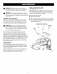


• Placeascrewdriverintheholeprovidedinthebearing
plate.
• Placeoneofthenon-cuttingteethlocatedbehindeach
carbide-tippedcuttingtoothagainstthescrewdriveror
pinandlockthebladeto preventit fromrotating.DO
NOTlockthebladeagainstoneofthecuttingteeth.
Carbidetipswillbreak.
• Usinga3/16in.hexkey,removethebladescrew.
NOTE:Turnthebladescrewcounterclockwiseto
removetheblade.
SCREWDRIVER
NON-CUTTING
TOOTHBEHIND
CARBIDE-TIPPED
CUTTINGTOOTH
HEXKEY
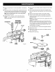
• Remove the outer blade washer, blade and inner blade
washer.
• Clean wood particles and resin from the blade wash-
ers, dust bag area, base assembly, and all surrounding
parts.
• Place the inner blade washer on the gear spindle.
• Place the new blade onto the shoulder of the blade
washer and secure with the outer blade washer and
the blade screw.
NOTE: The blade screw fits into the cupped side of the
outer blade washer.
NOTE: The blade teeth point toward the right of the
tool when held in normal operating position. The direc-
tion of rotation is marked on the joiner blade. An arrow
on the bottom of the front base assembly also indi-
cates direction of rotation.
• Turn the blade screw clockwise and tighten securely.
• Replace the shoe.
• Replace the washer and screws and tighten securely
with a screwdriver.
• Replace the dust bag.
BLADE
BLADE
SCREW
Fig. 23
BLADE
OUTER _ SCREW
BLADE _
WASHER
BLADE._._ _
INNERBLADE I
WASHER _ GEAR
SPINDLE
Fig. 24
21