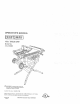
_ WARNING: To reduce the risk of injury, the user must read and 'Jnderstand the operator's manual before using this product. Customer Help Line: 1-800-932-3188 Sears, Roebuck and Co., 3333 Beverly Rd., Hoffman Estates, IL 60179 USA Visit the Craftsman web page: w_,.sears.
[] Waoanty ........................................................................................................................................................................ Introduchon ..................................................................................................................................................................... I_ General Sa(ety Rules ...........................................................................................................................
A WARNING: Read and gone. Failure may result persona_ READ limitations POWER [_ GUARD CONTACT SI-IOCK WITH pipes, AREA invge from Cluttered expose to rain. Keep CHILDREN the work AND cord MAKE WORKSHOP AWAY. All visitors master switches, B DON'T FORCE or by removing TOOL. safer at the feed 8 USE RIGHT purpose Don't starter padlocks it was and B keys. PROPER and of moving breakage of pans, your extension cord heavy wilt draw.
work or around or over the blade while blade is rotating. Do not attempt to remove cut material when blade is moving, [] BLADE COASTS AFTER BEING TURNED OFF. e NEVER USE IN AN EXPLOSIVE ATMOSPHERE• Normal sparking of the motor could ignite fumes. B INSPECT TOOL CORDS PERIODICALLY• If damaged, have repaired by a qualified service lechnician at an authorized service (acillty.
f_ NEVER perform means any operation using only your workpiece, Always fence to posRion "|reehand" hands use either and guide the rip tence ste,_d or t'_ve any part with of fhe saw NEVER reach behind, the brads or cutter _, MOVE THE either RIP FENCE the or miler of your body in line blade. over, or within with or guide the work.
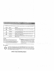
Some ofthefollowing symbols may beused onthis toolPlease study them and learn their meantng, Proper • interpretation ofthese symbols willallow you tooperate thetool better and safer, SYMBOL NAME DESIGNATION/EXPLANATION V Vogs VoJtage A Amperes Current Hz Hertz Frequency W Watt Power Minules Time rain Alternating Direct Current No Load [] Class @ Wet Conditions © A @ @ @ Read Rotational II Construction Per Minute @ Type or e characteristic Speed ..
The following signal words SYMBOL SIGNAL MEANING DANGER: Indicates an imrninent!y result in death or $er cos hazardous iiljury, WARNING: indicates a potenhaliy hazardous _esult in death or selbus illjur'j• CAUTION: Indicates a potentia ly hazardous situation, result in minor or moderate iniury. CAU'[ION: (Without propelly A and meanings are intended to explain Safely Alert Symbol) damage. SERVICE of nsk associated siluatlon, situat Indicates _-_\ WARNING: Servicing requites e×trome c
EXTENSION CORDS ELECTRICAL Use only 3-wire extension cords that have 3-prong grounding plugs and 3-pole receptacles that accept the tool's plug. When using a power tooi at a considerable distance from the power source, use an extension cord heavy enough lo carry the current that the tool will draw. Art undersized extension cord will cause a drop in line voltage, resulting in a loss of power and causing the motor to overheat.
• 'i ...... Anti-Kickback Pawls (radial arm and table saws) A device which, when properly installed and maintained is designed to stop the workplace from being kicked back toward the front of the saw during a ripping operation. Arbor The shaft on which a blade or cutting tool is mounted. Bevel Gut A cLltting operation re,ado with the blade at any angle ether than 90_ to the tab{e sudace. Chamfer A cut removing a wedge from a block so the end (or part of the end) is angled rather than at 90".
PRODUCT SPECIFICATIONS Blade Arbor .............................................................. 5/8 in. Blade Diameter .......................................................... 10 in. Blade Tilt ................................................................. O° * 45° Rating .............................................. 120 V, 50 Hz, AC Input .. .............................................................. 15 Amper_ No Load Speed .................................................
KNOW YOUR TABLE SAW See Figure 2. Before with attemptin G to use fins aroduct, at operating ADJUSTING features CLAMP ana safety - This cramp faml iarize the miter _s thrown workpiece. or reduce BLADE with opera;or: The, f[om be Ouilec starl the exact scale blade with adlusting a 36-1ooB" hardwheel. _evel - A _turdy with on lhe frort Dreclse measurements I 0 In. SLIDING MtlTER TABLE with allowing rne coclater sew table.
i -•- • • i OPERATING COMPONENTS _ WARNING: Atways remove the switch key when The upper podioo of the blade pro}ects up through the tabie and is staTounded by an insert called the throat plate. The height of the blade is set with a handwheel on the front of the cabinet. To accommodate wide panels, the saw table has rails on each aide, Detailed instructions are provided in the Operation section of this manual for the basis cuts: cross cuts, miter cuts, bevel cuts, and compound cuts.
BLADES _ For maximum performance, use the Craftsman blade provided the same it is recommended 36-tooth, with high quality your 10 in. carbide saw, Additiona_ are available such as ripping, Your local complete information, dealer that you combination blade for specific can provide styles of operat one WARNING: Do no_ use blades raled less than speed of this tool. Failure to heed this warning ( ould result in personal injury.
The following items are included wilh your table saw: 6 A. Rip Fence ................................................................................................................................................................... B. Large Blade Wrench ................................................................................................................................................... C. Smalt Blade Wrench ....................................................................
UNPACKING MOUNTING HOLES This product IJ requires assembly. This toot comes Carefully lift saw from the carton work sudace. NOTE: This too! is heavy. and place To avoid your knees bent and lift with and get help when reeded. back it on a level injury, your legs, keep nat your back, remove mounled the leg stand, to a leg stand. the table firm _upporfing surface Four have been this bolt holes porpose.
TOOPEN/CLOSE (SET-UP/TEAR TEAR DOWN DOWN) THE LEG STAND See Figure 7. To open (set-up} tt_e leg stand: m Step l:Withthe saw table on endand standing to theside, use your left hand to pull the _egstand latch towards you. 13 Sten 2: Once the leg stand is released from the table saw base, ease the legs of tl_e sland down. S±e__.3_: Grasp the upper leg support below the saw cabinet. Ste_: Keeping your left hand clear of the leg stand, pull the leg stand up until it locks into place.
TO STORE THE SeeFigures3The table saw TABLE SAW TO MOVE THE LEG STAND ACCESSORIES See Figure 10. g. has two convenient either side ot the saw cabinet) storage specifically areas To move the leg stand: (one on desigt_ed [er net in see, store ping each accessory the accessories securely S[_d _e_ the saw's accessories. When I Holdin 9 _#i e the _egstand t_waldl you until the leg stand and saw are balanced en the wheels.
i TO CHECK SAW BLADE See Figure !2 CAUTION: must To work point down to do so could INSTALLATION properly, the saw tile blade NOTE: Arbor shaft damage has left the saw blade M_ke sure the beret the left. Raise the the height!bevel To loosen B the to the saw oh the side af the saw cabinet. {a TO install the miter lence to the eliding miter table, I)oosen the adjusting clamp knob so the bolt has enoug!l clearance to slide into the table slot. Failure blade, the hand threads.
TO INSTALL See Figure Prober BLADE installation align guard and spreader the spreader ing on the table Lower ASSEMBLY of the blade that the saw blade ALWAYS GUARD AIITI-KICKBAI_K PAWLS 14. assembly means are in aligrlmenl. to the saw blade prior to turn saw. the blade. i la Install the blade using guard assembly the wing nut. Partially Check the blade and spreader NOTE: Blade alignment to !he mounting retighten with the wing plate SPRE!'_ER nul alignment.
APPLICATIONS You may use this tool forthepurposes listed below: Straight line cutting operations such ascross cutting, ripping, mitering, beveling, and compound culting _ Dadc ormolding outs with optional accessories [] Cabinet making and woodworldng NOTE: This table saw isdesigned tocutwood and wood composition products only.
T'_'PES OF CUTS See FTgure17 There are six basic cuts: 1) the cross cut, 2) the rip cut, 3) the miter cut, 4) the bevel cross cut, 5) the bevel rip cut, and 6) the compound (bevel) miter cut. All other cuts are combinations of these basic six. Operating procedures for making eacb kind of cut are given later in this section.
FEATHERBOARD HOW TO MOUNT A featherboard is a device used to belp control the workpiece by guiding it securely against the table or fence. Featherbeards are especially useful when ripping smalr workpieces and for completing non-through cuts. The end is angled with a number of short kerfs to give a frict on hold on the wcrkpiace and locked in place on the taoie with a C-clamp Test to ensure it can resist kickback.
.... TO CHANGE CHECKING SLIDING MITER TABLE AND BLADE DEPT_ See Figure 20. tVIA_(ING The blade depth should be set so that the outer points cff tile blade are higher than the workpiece by approximately 1/8 in. to 1/4 in. but the lowest pmnts {gullets) are below the top surface. ADJUSTMENTS TO POSITION THE SLIDING MITER TABLE See Figures 22- 23 A slide bolt is located on the front of the sew between the saw tab e and the front sos e.
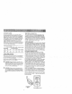
Fig. 23 TO CI-IEOK MITER See Figures _a Unplug BASE PARALLELISM 24 - 25. the saw. B Set saw up as if you were Tighten rail ciamps, clamp, preparing miter locking table (A) to the front of miter base as it will go. Place a reference the miter table NOTE: Place Front Place distance table NOTE: betweet_ P]ace square blade.
TOADJUST THE MITER BASE TO See Figure See Figure 26.
TO ADJUST QUICK-STOP RIP FENCE BLADE See Figure 28 SCALE The quick-stop is preset at the factory to stop the miter fence at exactly 0°, However, when sliding miter table adluslments are made, these adjustments may cause the quick-stop to need adjusting. Ci_eck quick{ stop with miter scale set at 0 _, If adjustments are needed, proceed with lhe folIowing steps: B Loosen the eccentric screw holding the quick stop. B Place the quick-stop against the miter fence with miter scale set at 0 °.
TO USE OUTFEED SUPPORT See Figure 31. The ouLffeedsuopod slides to give the operator additional support for cutting long workpieces. m With the table saw in the OFF position, stand behind the saw. 13 Grasp the outfeed suppod with both hands and pull it ur_t_lit is _ulb]extended TO USE THE TABLE EXTENSION See Figure 32 Tile table extension provides the operator with additional table width for supporting wider workpieces.
HEELING (PARALLELING) See Figures33 -35. _'_ WARNING: THE BLADE The blade must be square so the wood does not bind resulting in kickback, Failure to do so could result in serious personal injury. Do not loosen any screws for 1his adjustment uf_ti!yot_ have checked with a square and made test cuts to be sure adjustments are necessary. Once the screws are loosened, these items must be reset B Lift the blade guard.
MAKING CUTS The blade provided with lhe saw is a high-quaiity combination blade suitable for ripping and cross cut operations. _ WARNING: Do not use blades rated tess than the speed of this tool. Failure to heed this warning could result in personal il,iury. Use the miter gauge when making cross, miter, bevel and compound miter outs. To secure the angle, lock the miter gauge in place by twisting the leak knob clockwise. Always tighten the tack knob securely in place before use.
Place asupport (the same height assaw table) behindMAKING A MITER CUT thesaw forthecutwork, See Figure 39. I Make sure thewood IscIear oftheblade before turningIt is recommended you make test cuts on scrap wood. = onthesaw. Use apush block orpush stick tomove thewood WARNING; Make sure the blade guard assembly _ through thecut past theblade. Never push asmall is installed and woddng properly to avoid poasible piece ofweed into theblade with your hand; always serious injury. use apush stick.
VIEWEDFROr_THE FRONT,BELOWTHETABLESAW MAKING HEIGHTIBEVEL ADJUSTING HANOWHEEL A BEVEL RiP CUT See Figure 42. It is recommended you make test cuts oil scrap wood. TO LOOSEN i I I I WARNING: The np fence must oe on the let. side I of the blade to avoid trapping the wood and c_usinil kickback. PIacement of the rip fence to the righl I of the blade will result in kickback and the risk of seedus personal inlury.
When the cut is made, blade to come turn the saw off. Wait to a complete stop be[ore Ior the _emoving la Loosen tire workplace. After the blade cutoff stGck. 0 Grasp has stopped remove the power B Position the workplace from the lead end (the end fed first) and carefully remove it from against full speed the knob to the desired m Turn the flush Ihe workplace !/1o lhe blade table. completely, tile lock gauge B Advance gauge.
MAKING A LARGE PANEL CUT MAKING A NON-THROUGH See Figure 45, See Figure 44. Make sure the saw is p_opetly secured ta a work surface to avoid lipping from the weight of a large panel. WARNING: Non-through cuts can be made with the grain (ripping) _1 across the grain (cross cut}, The use of a non-through cU is essential to cutling grooves, rabbets, and dadoes.
MAKING A DADO CUT ,& WARNING: making Never feed wood any nan through dadoes. blocks, To avoid push personal slicks, with cut such iniury, your hands as rabbets always when See _Tgute 46. or As optional use push is requi_ed and featherboards. I dado throat the cut is made. blade to come workaiece. 13 Unplug D saw stop off.
_ WARNING: Before performing any adjustment, make sure the fool is unplugged _ supply. Faiture serious personal saw Blades might coast can occur cuts. become necessary due to wear. To avoid unnecessary practice is to check making adjusfments made TO some See Figures D Unplug shipping. carefully with cuts in scrap checked a good a tram- wood before Do not start with a square any and are needed. BLADE 47 - 49.
TO CHECK AND ALIGN THE SPREADER, BLADE, AND BLADE GUARD ASSEMBLY SAW TO CHECK THE ALIGNMENT TO THE BLADE OF THE RIP FEN_ See Figure 50 See F_?ure 51. If the blade guard assembly is out of alignment with the saw blade, adjust the alignment of the blade g[Jard assembly. The spreader must be aligned with the saw blade. e Raise the locking lever to permit the rip fence to be moved. Unplug the saw. To check allgnmm_t of the spreader: e UnpJug Ihe saw.
B If the two dimensions screws B Retighten 8 Make are not the same, on the fence and loosen the two align it. the two screws. two or three test cuts on scrap wood. If the cuts are trot true, repeat the process.
_ WARNING: When servicing, use only identical replacement parts. Use of any other parts may create a hazard or cause product damage. _ WARNING: Always wear safety goggles or safety glasses with side shields during power tool operation or when blowing dust. If operation is gusty, also wear a dust mask, L_ Periodically check all clam bolts for tightness and condition. plate is in good condition and in position. Check the blade guard assornbly.
PROBLEM CAUSE Excess vibration. Blade is out Blade is damaged. Saw is not Work SOLUTION el balarce. mour_led surface securely. Replace blade. Replace blade. Tighten is uneven. all hardware. Reposition on fiat SlJdace Adjusl legs of optional stand Check saw bJade insta latices. Replace blade i Blade is warped necessary, Rip fence does smoothly. Rip fence does not move Rip fence not mounted correctly. Remou_L the rip fence. Rails are dirty, or sticky. Clean and wax rails.
• I PROBLEM CAUSE SOLUTION Saw does notmake accurate Positive stops inside cabinet need Adjust positive stops. gO' or45'cuts. adjusting (Bevel Cuts). Miter gauge ismisaligned (Miter Adjust themiter gauge• Heighbtbevel adjusting hand- Gears orscrew post inside wheel ishard toturn. cabinet are clogged with saw dust Cuts). Molor cord or wall cord is not Saw does notslarL pklgged Plug inmotor cord orwall cord. in. Circuit iuse Circuit breaker Cord Clean thegears orscrew post. Replace circui[ fuse.
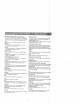
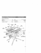
CRAFTSMAN _ 10 in. TABLE SAW - MODEL NO. 315,218060 / -'/, . : ",:- Figure B 48 49--4 Figure A 21 143 74 76 72 81 94 ._105 110 104 115 112 NOTE : The assembly shown represents 113 an important part of the double insulated possibility of alteration or damage to the system, service sheuld be performed Center. Contact your nearest Sears retail stere for service cerder information. 4! syslem.
CRAFTSMAN 10 in. TABLE SAW - MODEL NO. 315.218060 The model number will be found on a plate attached to the motor housing. Always mention the model l number n a correspondence // regatdin 9 your Table Saw or when order ng repa r paris. PARTS LIST (ey No. PaN Number Description 1 0134011803 Hear Rai;................................... 2 0134010211 3 0134010308 4 0134010!03-126 End Cap, Rear Rail ................... 2 Rail Holder Nut .......................... 4 Extension Table .........
CRAFTSMAN 10 in. TABLE SAW - MODEL NO, 315.218060 The model number in allnumber correspondence will be found regarding on e plate your attached Tab e Saw to or thewhen motor ordering housingrepair Always parts.mentioiq the model Key No. 91 92 93 94 95 96 97 98 99 J 1 PARTS LIST Qty. Key No. Part Number 9134015330102 Label, BeveiAng'e .................... 1 410011027 *Hex Hd. Screw {M6 x 70 ram}.,, 1 117 118 0131010318 0134010331 0134010318 Bracket, Motor ..........................
CRAFTSMAN _', 10 in. TABLE FIGURE SAW - MODEL A: SLIDING MITER NO, 315.218060 TABLE l Key Part No. Number Description Qty. A134010802 Sliding Miter Table Assembly (incl. Key No. 1 - 8) I 410561013" "Screw w/Washer (MSx 16 mini .,..4 2 0134010104-126 MiterTabie ................................... 1 8 3 4 5 6 0134010910 0181010501 0134010802 0134010216 7 410181001*' 8 0134010309 "Standard Hardware Item - May Be Purchased Locking Pin ................................. Quick-Stop ...............
Part Number A134014001 Description Qty. Height/Bevel Assembly Adjusting Handwheel .................................................1 00001 !0812 Nut (1/4 in. - 20) ......................... 0134010221-130 BeightLBevel Adjusting 3 4 5 6 8 9 10 Handwheel 412012041 0121010223 0101140203 0121010224 0134010222 414011003 0134010905 A121015201 1 ................................. 1 Flat Washer (6+5 x 13 x 1.57)....1 Bevel Handle ............................. 1 Screw ..................................
CRAFTSMAN 10 in. TABLE 3t SAW - MODEL NO. 315.218060 d 27 ¼ 13 24 22 42 23 3s-4,' : 20 REPLACEMENT I Key No. 1 2 3 4 5 6 7 8 9 10 11 12 13 14 15 Pa_ Number 0131011301 O131O10322 0131010810 0131010323-126 411011707 412041702 411071702 0131010915 A134017001 0131010923 410031014 0131011302 401451708 0512010812 412011111 15 0134010327 I7 0134010235 18 19 0134010240 410011028 20 21 0134010243 A134016301 22 0131010918 23 0131010232 126 PARTS Description FOR Qty.
I !, ,il m _w m
Get it fixed, at your home or ou 's! Your Home For repair-in your home of all major brand appliances, lawn and garden equipment, or heating and cooling systems, no matter who made it, no matter who sold it! For the replacement pads, accessories and owner's manuals that you need to doqt-yourself. For Sears professional installation of home appliances and items Tikegarage door openers and water heaters. I°800-44VlY-HOi_tiE ® (!-800-469-4663) Carl anytime, day or night(U,S.A, www.sears.com and Canada) www.