Operator's Manual [RAFTSMAN.° 18-Inch Straight Shaft/31 cc/2-Cycle GAS-POWERED BRUSHWACKER ® Brushcutter/Trimmer Model No. 316.74520 • • • • • • ,_ manual and follow all its Safety Rules and WARNING: Before using this product, read this Operating Instructions. Sears, Roebuck, and Co., Hoffman OPERATOR S MANUAL PART NO. 769-00066 PRINTED IN U.S.A. Safety Assembly Operation Maintenance Parts List Espa_ol Save this manual for future reference.
Warranty Statement 2 Maintenance 17 California Proposition 65 Warning 2 Service and Adjustments 19 Spark Arrestor 2 Storage 23 Rules for Safe Operation Contents of Hardware Pack 3 Specifications 23 Assembly 7 8 Troubleshooting EPA Operation 12 Chart 24 26 Parts List 27 Espa_ol E1 FULL ONE-YEAR WARRANTY ON CRAFTSMAN ® GAS-POWERED BRUSHWACKER ® BRUSHCUTTER/'rRIMMER For one year from the date of purchase, when this Craftsman Gas-Powered Brushwacker Brushcutter/Trimmer is maintained
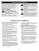
The purpose of safety symbols is to attract your attention to possible dangers. The safety symbols, and their explanations, deserve your careful attention and understanding. The safety warnings do not by themselves eliminate any danger. The instructions or warnings they give are not substitutes for proper accident prevention measures. SYMBOL MEANING ,_ DANGER: Failure to obey a safety warning will result in serious injury to yourself or to others.
WHILE OPERATING • Stop and switch the engine to OFF for maintenance, repair, or for changing the cutting attachment or other attachments. • Never start or run the unit inside a closed room or building. Breathing exhaust fumes can kill. Operate this unit only in a well ventilated area outdoors. • Use only genuine Craftsman® replacement parts when servicing this unit. These parts are available from your authorized service dealer.
AFTER USE Allow the engine to cool before storing or transporting. Be sure to secure the unit while transporting. • Clean cutting blade(s) with a household cleaner to remove any gum buildup. Oil the blade(s) with machine oil to prevent rust. Store the unit in a locked up and dry, or high and dry place to prevent unauthorized use or damage. Keep out of the reach of children. • Lock up and store the cutting blade in an appropriate area to protect the blade from unauthorized use or damage.
SYMBOL MEANING • PRIMER BULB Push primer bulb fully and slowly, 5 to 7 times. • UNLEADED FUEL Always use clean, fresh unleaded fuel. • INDICATES OIL Refer to operator's manual for the proper type of oil. A B C • CHOKE B C CONTROL PARTIAL choke position. RUN position. • HOT SURFACE WARNING Do not touch the engine or muffler. These parts get extremely hot from operation. When turned off they remain hot for a short time.
18" Cutting Attachment Shield Locking Rod Tool Operator's Manual (3) Screws (1/4-20 x 1/2) - for Cutting Attachment Shield 4-Tooth Blade Blade Nut Bottle of Oil Shoulder Harness -7- 44-Tooth Blade
Your unit can be assembled in three (3) configurations: ]1 CUTTING ATTACHMENT and light weeds. -- used for cutting grass 4-TOOTH BLADE -- used for cutting grass, weeds. and woody brush up to 1/2 inch in diameter. I i iiii ii i i_iiii iii!I_ u 44-TOOTH BLADE -- used for cutting grass, weeds, and woody brush up to 2 inches in diameter.
TOOLS REQUIRED • 5/8 inch Closed-Ended FOR ASSEMBLY Remove the cutting attachment shield from the shield mount by removing the three (3) screws with an appropriate screwdriver (Fig. 4). Store parts for future use. Wrench (if installing blade) • Flat Blade Screwdriver • Large Phillips Screwdriver INSTALLING HANDLE AND ADJUSTING Assist Handle THE ASSIST (4) Installing 1. Remove the screws and nuts, and the top and middle clamp pieces that were installed on the assist handle for shipping. 2. 3.
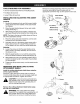
TO REMOVE CUTTING AND INSTALL BLADE A ,_ _!_ WARNING: F.=.=.=.=.=.=-=-=-_ ATTACHMENT Output Shaft TO avoid serious personal injuryl Output always wear gloves while handling, removing, or installing the blade(s) or cutting attachment. _ Shaft Hole Locking WARNING: The gear housing gets hot after long periods of use. TO avoid serious personal injury, do not touch the housing until it has cooled. /__--___)/ _ Rod Slot Locking Rod _ J_ __.
TO REMOVE BLADE AND INSTALL ATTACHMENT jl_ A" CUTTING Adjust the shoulder harness for balance so that the cutting attachment is level with the ground. A properly adjusted shoulder harness will support the entire weight of the unit, freeing your arms and hands to guide and control the cutting motion. 4. WARNING: To avoid serious personal injury, always wear gloves while handling, removing, or installing the blade(s) or cutting attachment. .
_ Fig. 14 Fig. 13 KNOW YOUR Harness Shoulder Clamp BRUSHCUTrER/TRIMMER READ THIS OPERATOR'S MANUAL AND SAFETY RULES BEFORE OPERATING YOUR UNIT. Compare the illustrations with your unit to familiarize yourself with the location of various controls and adjustments. CHOKE CONTROL Save this manual for future reference. FUEL CAP STARTER ROPE GRIP ____ BLADE SHIELD THROTTLE ___ LOCK-OUT\ ON/OFF STOP \\ CONTROL PRIMER BULB _,/ 44-TOOTH SAW BLADE SHOULDER HARN_ THROTTLE ASSIST HANDLE SPARK PLUG ON/O
THIS ENGINE IS CERTIFIED TO OPERATE ON UNLEADED Use of Blended Fuels TO FUEL ENGINE If you choose to use a blended fuel, or if its use is unavoidable, the following precautions are recommended. CAUTION: Be sure to read these instructions carefully before attempting to start or operate this unit. Using old or improper oil or fuel. or improperly mixing the oil and fuel. can cause engine damage. This type of damage will VOID the engine warranty. 1. Always use fresh fuel mix. 2.
IMPORTANT Experience indicates that alcohol blended fuels (called gasohol or using ethanol or methanol) can attract moisture which leads to separation and formation of acids during storage. Acidic gas can damage the fuel system of an engine while in storage. To avoid engine problems, empty the fuel system before storage of 30 days or longer. Drain the fuel tank, start the engine and let it run until the fuel lines and carburetor are empty. Use fresh fuel next season.
HOLDING _ THE TRIMMER hearing, and body protection to reduce the risk offoot injury WARNING: Always wear eye, when operating this unit. Before operating the unit, stand in the operating position (Fig. 18). Check for the following: • The operator is wearing eye protection and Proper clothing. • The right arm is slightly bent, and the hand iS holding the shaft grip. • The left arm is straight, and the hand is holding the handle. • The unit is below waist level.
PROPER STANCE WARNING: Blade thrust may occur when the spinning blade contacts an object that it does not immediately cut. Blade thrust can be violent enough to cause the unit and/or operator to be propelled in any direction, and possibly lose control of the unit. Blade thrust can occur without warning if the blade snags, stalls or binds. This is more likely to occur in areas where it is difficult to see the material being cut. When operating the unit, maintain proper footing and balance.
MAINTENANCE SCHEDULE NOTE: Maintenance, replacement, or repair of the emission control devices and system may be performed by any nonroad engine repair establishment, individual or authorized service dealer. These required maintenance procedures should be performed at the frequency stated in the table. They should also be included as part of any seasonal tune-up. NOTE: Some maintenance procedures may require special tools or skills.
Cleaning the Air Filter f 1. Remove air filter/muffler cover. See Removing the Air filter/Muffler Cover in the Maintenance section. 2. Remove the air filter from behind the air filter/muffler cover (Fig. 24). 3. Wash the filter in detergent and water (Fig. 25). Rinse the filter thoroughly. Squeeze out excess water. Allow it to dry Completely. Apply enough clean SAE 30 oil to lightly Coat the filter (Fig. 26). 4. 5. Squeeze the filter to spread and remove excess oil (Fig. 27), 6.
TO CLEAN \ UNIT Do not use any strong detergents on the plastic housing or the handle. They can be damaged by certain household cleaners that contain aromatic oils such as pine and lemon, and by solvents such as kerosene. Wipe off any moisture with a soft cloth. Reel Housing before servicing cutting attachment.
2. Place your index finger between the two lines to stop the lines from overlapping (see Fig. 32). 3. Wind both lines at the same time in even and tight layers onto the reel, in the direction indicated on the reel (Fig. 32). NOTE: Failure to wind the lines in the direction indicated will cause the cutting head to operate incorrectly. 4. insert one line end into each holding slot (Fig. 33). Reinstalling the Reel Reel F-- 1.
CARBURETOR ADJUSTMENT NOTE: The cutting attachment should not rotate when the engine idles. The idle speed of the engine is adjustable though the air filter/muffler cover (Fig 35). 3. NOTE: Careless adjustments can seriously damage your unit. Any nonroad engine repair establishment, individual or authorized service dealer should make carburetor adjustments.
SPARK ARRESTOR Note: 1. 2. 3. 4. 5. 6. 7. 8. MAINTENANCE The flow of the exhaust can be in one direction only: AWAY from the engine. Pay close attention to how the muffler assembly is put together, so you can put it back together exactly as it was. Failure to do so will damage the unit and may cause serious personal injury. ! ! ! ! Remove the air filter/muffler cover. See the instructions in this manual for removing the cover.
It is important to prevent gum deposits from forming in essential fuel system parts such as the carburetor, fuel filter, fuel hose or tank during storage. Also, experience indicates that alcohol blended fuels (called gasohol or using ethanol or methanol) can attract moisture which leads to separation and formation of acids during storage. Acidic gas can damage the fuel system of an engine during storage.
TROUBLE CAUSE Engine will not start On/Off Stop Control is "OFF" position Turn On/Off Stop Control to "ON" Empty fuel tank Fill fuel tank Primer bulb wasn't pushed enough Press primer bulb fully and slowly 5-7 times.
- 25 -
California / EPA Emission Control Warranty Statement; Your Warranty Rights and Obligations The California Air Resources Board, EPA (Environmental Protection Agency), and Sears, Roebuck, and Co. are pleased to explain the emission Control System Warranty on your 2000 and later small off-road engine. In California and the 49 states, new small off-roed engines must be designed, built and equipped to meet the state's stringent anti-smog standards.
I I L\ @ @ Item 1 2 3 4 5 Part No.
® / ® Item Part No.
Manual del Operador [RAFTSMAN.+ Eje Recto de18 pulgadas/31 cc/2 ciclos RECORTADORA DE LINEA BRUSHWACKER ®A GASOLINA Modelo No. 316.74520 • • • • lea este manual y siga sus Reglas de seguridad ADVERTENCIA: antes de usar este producto, e Instrucciones de operacibn, Sears, Roebuck, and Co., Hoffman Seguridad Ensamble Operacibn Mantenimiento Guarde este manual para referencia futura. Estates, IL 60179 USA 2/02 Revl MANUAL DEL OPERADOR, PARTE N ° 769-00066 IMPRESO EN LOS EE.UU.
Declaraci6n de Garantia Limitada E2 Mantenimiento Advertencia de la Proposici6n 65 de California E2 Parachispas Normas para una operaci6n segura Contenidos de la Bolsa de Piezas E2 E3 E7 Servicio y Ajustes Almacenamiento Ensamble E8 Operaci6n E12 Especificaciones Resoluci6n de Problemas E17 E19 E23 E23 E24 EPA E27 GARANTIA TOTAL DE UN AI_IO PARA LA CORTADORA DE MALEZAS / RECORTADORA CRAFTSMAN@ BRUSHWACKER® A GASOLINA Sears reparar& sin costo alguno cualquier defecto de material o de mano de
Los simbolos de seguridad se utilizan para Ilamar su atenci6n sobre posibles peligros. Los slmbolos de seguridad y sus explicaciones merecen toda su atenci6n y comprensi6n. Los simbolos de seguridad no elirninan ningQn peligro por si mismos. Las instrucciones o advertencias que ofrecen no substituyen las medidas adecuadas de prevenci6n de accidentes. SJMBOLO ,_ PELIGRO: El no obedecer una advertencia de seguridad puede conducir a que usted u otras personas sufran graves lesiones.
DURANTE LAOPERACION • Si goipea o se enreda con algQn objeto extrafio, apague el motor de inmediato y verifique si hay daSos. No opere la unidad antes de reparar los daSos. No opere la unidad si tiene piezas flojas o daSadas. No opere la unidad con una cuchilla torcida, rajada o desafilada. Deseche las cuchillas que est6n torcidas,encorvadas, rajadas o rotas. • No arranque ni opere la unidad en una sala o edificio cerrado. Los gases de escape de mon6xido de carbono pueden ser letales en un &tea cerrada.
• Si siente una vibraci6n excesiva, apague el motor DE INMEDIATO. La vibraci6n indica que hay problemas. Inspeccione si hay tuercas o pemos flojos o dafios antes de continuar. Repare o cambie las pares afectadas segQn sea necesario. • Espere que el motor se enfrie antes de guardar o transportar la unidad. Asegerese de que la unidad est6 segura al transpor_arla.
S|MBOLOS SIGNIFICADOS 5-7x • BombUla del cebador N Presione la bombilla del cebador completa y lentamente, de 5 a 7 veces. • Combustible sin Plomo Use siempre combustible • Indicador limpio y nuevo sin plomo. de Aceite Consulte el manual del operador para informarse sobre el tipo adecuado de aceite.
Varilla de cierre Protectoraccesorio de corte de 18" Manual del operador (3) Tornillos (1/4-20 x 1/2) - para el protector accesorio de corte Cuchilla de 4 dientes Tuerca de la cuchina (tamat_oreal) Arn_s para el hombro Botella de aceite - E7 - Cuchilla de sierra de 44 dientes
Su unidad puede ser ensamblada en tres (3) configuraciones: CUCHILLA DE 4 DIENTES -- se usa para cortar cesped, hierbas y arbustos le_osos de hasta 1/2 pu/gada de di&metro. ACCESORIO DE CORTE -- se usa para cortar cesped y hierbas deigadas. CUCHILLA DE SIERRA DE 44 DIENTES -- se usa para cortar cesped, hierbas y arbustos lefiosos de hasta 2 pulgadas de di&metro.
HERRAMIENTAS NECESARIAS PARAELENSAMBLE Manija Au xiliar_ • Llave de boca cerrada de 5/8 de pulgada (si instala la cuchilla) • Destornillador de v&stago piano • Destornillador Phillips grande INSTALACI_)N Y AJUSTE DE LA MANIJA (4) AUXILIAR superior Instalaci6n 1. Abrazadera Retire los tornillos y las tuercas, asi como las abrazaderas superior y media que se instalaron en la manija auxiliar para el envio. 2. Coloque la manija auxiliar entre la abrazadera media y la abrazadera superior (Fig.
REMOCION DEL ACCESORIO DE CORTE E INSTALACI6N DE LA CUCHILLA Ejedesalida ADVERTENCIA: Para evitar graves lesiones personales, use siempre guantes al manejar, sacar o instalar !a(s) cuchi!la(s) o el accesorio de corte. 45, _ _ Ranura de la __----------_-_J.} varilla de cierre __<_ Orificio ADVERTENCIA: El bastidor de los engranajes se calienta mucho despu6s de largos perfodos de uso. Para evitar graves lesiones personales, n0 toque eI bastidor hasta que se haya enfriado.
REMOCION DE LA CUCHILLA E INSTALACIeN DEL ACCESORIO DE CORTE personales, use siempre guantes al lesiones manejar, sacar ADVERTENCIA: Para evitar graves o instalar la(s) cuchilla(s) o el accesorio de corte. _lb ADVERTENCIA: El bastidor de los engranajes se calienta luego de largos periodos de uso. Para evitar una grave lesi6n personal, no toque el bastidor basra que se haya enfriado. 4, Ajuste el ames para el hombro para darle equilibrio de modo que el accesorio de corte quede nivelado con el suelo.
×\ Fig. 13 CONOZCA SU CORTADORA Abrazadera del arn_s para el hombro Fig. 14 DE MALEZAS / RECORTADOR LEA ESTE MANUAL DEL OPERADOR Y LAS NORMAS DE SEGURIDAD ANTES DE OPERAR SU UNIDAD. Compare las ilustraciones con su unidad para familiarizarse con la ubicaci6n de los diferentes controles y ajustes. CONTROL DE Guarde eete manual para su referencia futura. OBTURACI(_N TAPA DEL COMBUSTIBLE ASA DE LA CUERDA PROTECCI(SN DE LA CUCHILLA DE ARRANQUE BLOQUEO DEL ACELERADOR CONTROL DE APAGADO ON/OFF \_ \ BOMBI
ESTE MOTOR PARA ALIMENTAR ESTA CERTIFICADO PARA OPERAR CON UNA MEZCLA GASOLINA SIN PLOMO Y ACEITE. Uso de Combustibles EL MOTOR de Mezcla Si usted decide utilizar un combustible mezcla o su uso es inevitable, le recomendamos que siga las precauciones siguientes. PRECAUCI6N: Asegt_rese de leer estas instrucclones con cuidado antes de intentar encenaer u operar esta unidad. El utilizar aceite o combustible viejos o no aaecua(]os puede daSar el motor. Este t_po de daSo ANULARA la garantla Gel motor.
IMPORTANTE NOTA: Si el motor se inunda al intentar arrancar la unidad, coloque la oalanca del obturador en la posici6n de MARCHA (RUN) (C) 141(Fig. 16). Oprima el control del regulador. Tire de la cuerda de arranque r&pidamente. El motor debe arrancar luego de tres (3) a ocho (8) tirones. La expefiencia indica que los combustibles con mezcla de alcohol (llamados gasohol o que usan etanol o metanol) pueden atraer humedad Io cual conduce a la separacidn y formacidn de &eidos durante el almaeenamiento.
COMOSOSTENER ELRECORTADOR jl_ AL. ADVERTENCIA: Use siempre protecci6n para sus 0jos, audicidn, pies y cuerpo para reducir el riesgo de una lesi6n al operar esta unidad. Antes de operar esta unidad, p_rese en posici6n de operaci6n (Fig. 18). Verifique Io siguiente: ,, El operador tiene protecci6n ocular y ropa adecuada. • El brazo derecho est& levemente doblado, y la mano estA sesteniend0 el mango del eJe• El brazo izquierdo est& recto, y la mano est,_ sosteniendo la manija.
POSICI6N ADECUADA ADVERTENCIA: Cuando la cuchilla giratoria hace contacto con un objeto que no corta de inmediato, puede ocurrir el impulso de la cuchilla. El impulso de la cuchilla puede ser Io suficientemente violento como para hacer que la unidad y/o el operador sean impulsados en cualquier direcci6n, y posiblemente perder el control de la unidad. El impulso de la cuchilla puede ocurrir si la cuchilla se tropieza, se traba o se atora.
NOTA: NOTA: Algunos procedimientos de mantenimiento pueden requerir el uso de herramientas o habilidades especiales. Si no est& seguro acerca de estos procedimientos, Ileve su unidad a un establecimiento de reparaci6n, persona o proveedor de servicio autorizado que arregle motores para uso fuera de la carretera.
2. Saaue los cuatro (4) tomillos que sostienen la cubier[a del filtro de aire / sileneiador (Fig. 23t. Use un destornillador de v_stago piano o an destomillador de broca 1"-20. 3. Saaae la cubierLa del motor. No la fuerce. f Limpieza del filtro de aire 1. Saaue la cubierLa del filtro de aire / silenciador. Vea Remoci6n de la cubierta del filtro de aire / silenciador en la seeci6n de Mantenimiento. 2. Saaue el fiitro de aire de atrAs de la cubier[a del filtro de aire / silenciador [Fig. 24). 3.
LIMPIEZA DE LA UNIDAD \ No use ningt]n detergente fuerte para limpiar el bastidor de pl&stico ni la manija. Estas piezas pueden daSarse ya que cier_os productos dom6sticos de limpieza contienen aceites arom&ticos como pino y lim6n, y solventes como el querosene. Seque toda la humedad con un paso suave. _lJ Bastidor del carrete unidad antes de realizar el servicio del ADVERTENCIA: Para evitar lesiones, apague la accesorio de corte.
2. Coloque su dedo indice entre las dos lineas para evitar que se superpongan (yea la Fig. 32). 3. Bobine ambas lineas al mismo tiempo en capas parejas y ajustadas sobre el carrete, en el sentido indicado en el carrete (Fig. 32). NOTA: Si no bobina las lineas en el sentido indicado, la cabeza de corte funcionar& en forma incorrecta. 4. _,o_ Inserte un extremo de linea en cada ranura de fijaci6n (Fig. 33). Reinstalaci6n del carrete 1.
AJUSTE DEL CARBURADOR NOTA: El accesorio de corte no debe girar cuando el motor est& funcionando en minima. La velocidad ]enta del motor puede ser ajustada por la cubierta del silenciador / filtro de aire (Fig. 35). 3. NOTA: Los ajustes realizados sin cuidado pueden da_ar seriamente su unidad. Los ajustes del carburador deben ser realizados por un establecimiento de reparaei6n, persona o proveedor de servicio autorizado que arregle motores para uso fuera de la carretera.
MANTENIMIENTO Nota: 1= 2. 3= 4= 5. 6= 7= DEL PARACHISPAS El flujo de las emisiones puede ser en una direcci6n solamente: APARTANDOSE del motor. Preste mucha atenci6n a c6mo se ensambla el silenciador, de modo que Io pueda volver a armar exactamente como est& El no hacerlo asr daSara a la unidad y pudiera causar lesiones personales graves. Silenciador Quite la cubierta del silenciador/filtro de aire. Yea las instrucciones que aparecen en este manual para quitar la cublerta.
Durante el almacenamieeto, es impor_ame evitar la formaci6e ae aep6sitos de goma en piezas eseeciales del sistema de combustible como pot ejemplo el carburador, el filtro de combustible, la manguera o el tanque de combustible. Adem&s. la experieecia nos indica que los combustibles con mezcla de alcohol (llamados gasohol o que usan etaeol o metanol) pueden atraer humedad. Io cual conduce a la separac_on y formaci6n de &cidos durante el almacenamiento.
PROBLEMA El motor no arranca El motor no funciona en minima CAUSA SOLUCION El control de apagado On/Off est& en posici6n de apagado ("OFF") Gire el control de apagado On/Off a arranque ("ON") El tanque de combustible Uene el tanque de combustible est& vacio La bombilla de cebado no fue oprimida Io suficiente Optima la bombilla de cebado total y lentamente de 5 a 7 veces.
- E25-
- E26-
DECLARACION DE LA GARANT|A DE CONTROL DE EMISIONES SUS DERECHOS DE CALIFORNIA / EPA; DE GARANT|A Y OBLIGACIONES La Junta de Recursos del Aire de California, EPA (Agencia de Protecci6n del Medio Ambiente), y Sears, Roebuck, and Co. tienen el gusto de explicar la garantia del sistema de control de emisions de su pequeSo motor todo-terreno del aSo 2000 y aSos ppsteriores.
For in-home major brand repair service: Call 24 hours a day, 7 days a week 1-800-4-MY-HOME Para pedir servicio de reparacibn s" (1-800-469-4663) a domicilio - 1-800-676-5811 In Canada for all your service and parts needs call - 1-800-665-4455 Au Canada pour tout le service ou les pieces For the repair or replacement parts you need: Call 7 am - 7 pm, 7 days a week 1-800-366-PART Para ordenar piezas con entrega (1-808-388-7278) a domicilio - 1-800-659-7084 For the location of a Sears Parts and Rep