
Operator`s manual


TO REMOVE CUTTING ATTACHMENT
AND INSTALL BLADE
A WARNING: TO avoid serious personal injuryl
,_ always wear gloves while handling, removing,
or installing the blade(s) or cutting attachment.
_!_ WARNING: The gear housing gets hot after long
periods of use. TO avoid serious personal injury,
do not touch the housing until it has cooled.
Use the following instructions and refer to the safety
warnings to properly remove the cutting attachment and
install the blade(s).
Place the unit upside down, on a workbench or the ground,
when removing and installing the cutting attachment or blade.
Remove the Cutting Attachment Shield
See Removing and Installing Cutting Attachment Shield
in the Assembly section.
Remove the Cutting Attachment
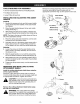
1. Line up the hole in the output shaft with the locking rod
slot. Insert the locking rod through the slot into the output
shaft hole (Fig. 5).
2. Hold the locking rod in place by grasping it next to
the boom of the unit (Fig. 6).
3. Screw the cutting attachment clockwise off of the
shaft (Fig. 7) and store for future use.
NOTE: The blade retainer under the cutting attachment
will be used when installing the brush blade(s).
Install a Brush Blade
NOTE: The 4-tooth brush blade is reversible, which can
be reversed by removing the blade, turning it upside
down, and reinstalling it. The 44-tooth saw blade is
NOT reversible and should be installed only as shown!
4.
Install the blade, blade retainer and lock nut (Fig. 8).
Insert the locking rod through the slot into the outout
shaft hole. Make sure that the blade stays flat and
centered against the output shaft while tightening
the lock nut counterclockwise (Fig. 9).
5. If you have a torque wrench tighten the lock nut to
325-335 in..Ibs (37-38 N.m), while holding the
locking rod in the slot.
If you do not have a torque wrench, hold the locking
rod in the slot. Rotate the lock nut counterclockwise
with a 5/8 inch closed-ended or socket wrench, until
the lock nut presses against the washer and the
blade is snug. Make sure the blade assembly is
installed correctly, then rotate the lock nut an
additional 1/4-1/2 turn (Fig. 9).
6. Remove the locking rod.
A WARNING: Do not sharpen either cutting
blade. Sharpening the blades can cause a blade
tip to break off while in use. This can result in
severe personal injury to yourself or others.
WARNING: Verify the blade is flat against the
output shaft after the lock nut is tightened. If
the blade is off-center, the unit will be damaged
by vibration, and the blade may fly off. which
can cause serious personal injury.
F.=.=.=.=.=.=-=-=-_
Output Shaft
Output _ /__--___)/
Shaft Hole
Locking _ J_
Rod Slot __.
Locking Rod _ V
Fig. 5
Fig. 6
Cutting Attachment
Locking Rod
Slot
Locking Rod
Lock Nut
Fig. 7
44-Tooth Blade
Locking
Rod
Blade Shield
J
Fig. 8
!/4-1/2 Turn
Fig. 9
-10-